
Fishing reel with uniform oscillation system

a technology of oscillation system and fishing reel, which is applied in fishing reels, applications, applications, etc., can solve the problems of unfavorable casting distance, unfavorable cosmetic and functional effects, and uneven line accumulation on the spool, so as to reduce dwell at the end of the stroke and uniform speed

Inactive Publication Date: 2006-04-11
PENN FISHING TACKLE MFG
View PDF9 Cites 5 Cited by
  • Summary
  • Abstract
  • Description
  • Claims
  • Application Information

AI Technical Summary

Benefits of technology

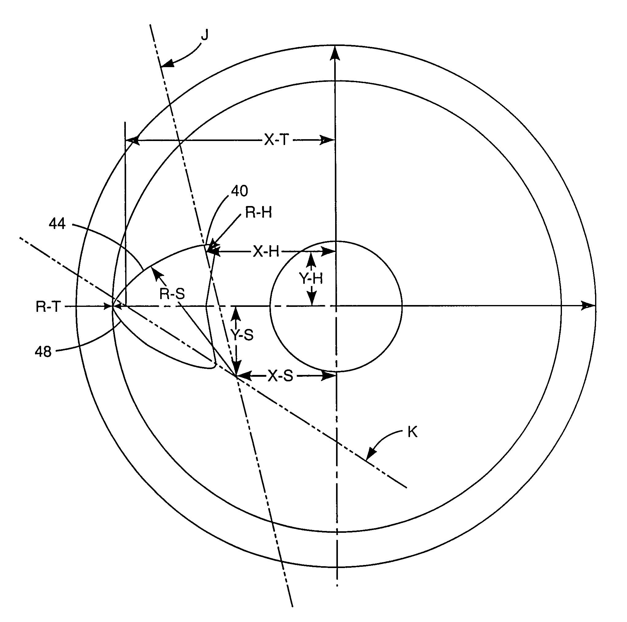
[0021]My invention is a fishing reel with an improved uniform oscillation system that has all the benefits of being durable, simple and compact, while also producing a line lay that is comparable to more complicated systems. This is accomplished by making improvements to the crosswind gear and block type system. These modifications allow the block to travel at a more uniform speed throughout the entire oscillation cycle by, among other things, reducing dwell at the ends of the stroke.

Problems solved by technology

Without this oscillation, the line would accumulate on the spool very unevenly.
This is cosmetically and functionally undesirable.
Performance problems resulting from uneven line lay are: (1) casting distance is adversely affected and (2) drag release (while fighting a fish) will not be as smooth.
However, the line lay is only somewhat uniform, and not flat across the length of the spool.
The second, the worm type, does give a flat line lay, but it is not durable and simple because there are more parts in the mechanism.

Method used


Image

  • Fishing reel with uniform oscillation system
  • Fishing reel with uniform oscillation system
  • Fishing reel with uniform oscillation system

Examples


Embodiment Construction

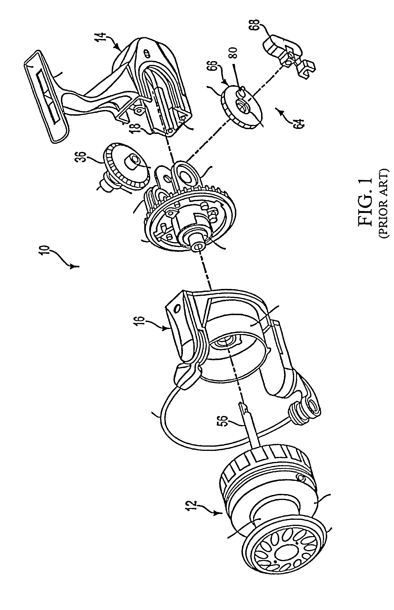
[0047]The prior art, as shown in FIG. 1, comprises a reel 10 having a spool 12, an oscillating spool main shaft 56, an oscillating assembly 64, a rotor 16, a drive gear 36, a crosswind block 68 and a rotating crosswind gear 66. As line 19 (FIG. 8) is laid on the spool 12 in accordance with the prior art, more fishing line is laid at the ends, as shown diagrammatically at numbers 11 and 13 on the spool 12. Each of the lines shown in this envelope (from L1 through L2) within the spool 12 represents a portion of the lay of the fishing line per the location of the pin 18. The shape P of the lay of the spool line is shown at 28. The oscillating travel of the spool shaft 56 is shown by the double headed arrow T. The movement of the crosswind block 68 is from the position shown in full lines to the position shown in phantom lines and return.

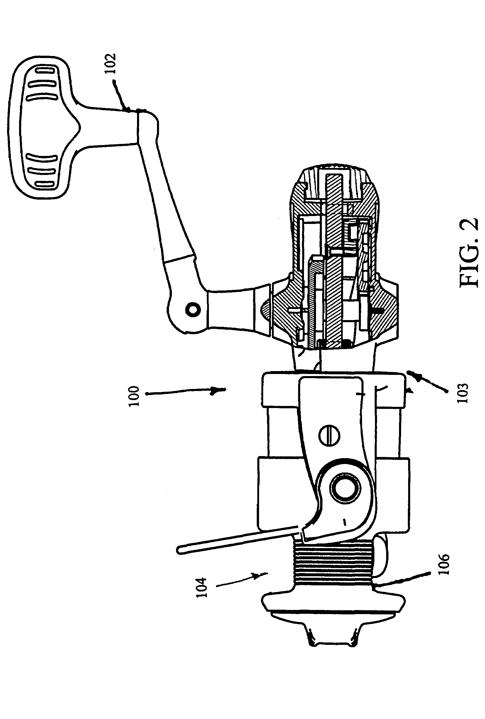
[0048]In my system, the fishing reel 100FIG. 2 comprises: a reel frame 103; a spool spindle means 104 mounted for reciprocation longitudinally in said ...


PUM


Abstract

A spinning reel has a level wind system wherein a slot is formed in the crosswind block. A lobe is carried on a crosswind gear. The surfaces of the lobe interact with the surfaces in the block. There are three curved surfaces on the lobe and four working surfaces in the block.

Description

[0001]This application is a continuation of my prior application Ser. No. 10 / 302,637, filed Nov. 21, 2002, now abandoned entitled “Uniform oscillation system”, which was a continuation-in-part of my prior provisional patent application, Ser. No. 60 / 343,441, filed Dec. 31, 2001; and incorporates both of those applications herein as if fully set forth.BACKGROUND OF THE INVENTION[0002]1. Technical Field[0003]This invention relates to fishing reels and particularly to a method and means of uniformly winding fishing line on to spinning reels.[0004]2. Description of the Art[0005]All spinning reels require some form of spool oscillation system that enables the spool to move back and forth as fishing line is being retrieved. Without this oscillation, the line would accumulate on the spool very unevenly. This is cosmetically and functionally undesirable.[0006]Prior art FIG. 1, shows an exploded view of parts of a fishing reel as disclosed in FIG. 3 of U.S. Pat. No. 6,394,379, issued May 28, ...

Claims


Application Information

Patent Timeline
Patent Type & Authority Patents(United States)
IPC IPC(8): A01K89/01
CPCA01K89/0114
Inventor WIEST, TIMOTHY A.
Owner PENN FISHING TACKLE MFG
Learn More