
Deinterlacing of video sources via image feature edge detection

Active Publication Date: 2006-04-04
LATTICE SEMICON CORP
View PDF29 Cites 102 Cited by
  • Summary
  • Abstract
  • Description
  • Claims
  • Application Information

AI Technical Summary

Benefits of technology

[0016]The present invention advantageously allows for the reduction of artifacts in deinterlaced video images. By correctly and accurately identifying edge features in the video image, a video deinterlacer can produce new pixel values derived from other pixels located along edge features in the image. The result is a progressive video image which is free of defects and deinterlacing artifacts. Further, the deinterlacing preserves the maximum amount of vertical detail in the image.

Problems solved by technology

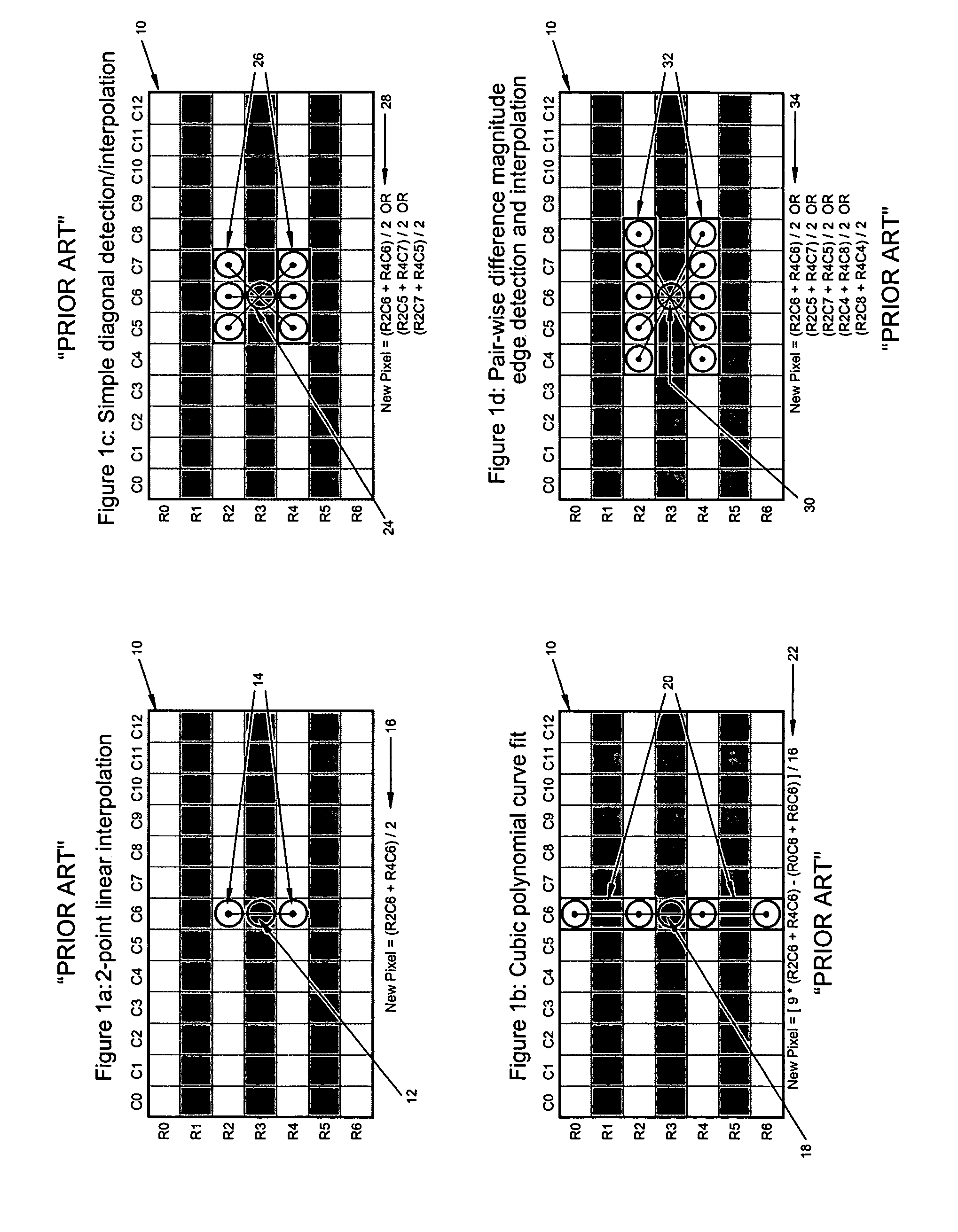
These vertically aligned pixel calculation techniques results in a loss of vertical resolution in the output image since computed pixels are based only on a single video field.
Since the human visual system is very sensitive to object edges or boundaries, this loss of vertical detail is often very noticeable on diagonal edges of objects, which appear to have a jagged or ‘staircased’ appearance.
An alternate technique used to calculate new pixel values is to take the median value of a number of pixels in the immediate area surrounding the pixel to be calculated, but this approach has met with limited success and often does not remedy the loss of vertical detail.
Some yield objectionable artifacts when the image feature detection either fails completely or yields an erroneous result.
All of the disclosed techniques suffer to some extent from the inability to recognize larger image features since all base image feature detection on a relatively small area around the calculated pixel position.

Method used


Image

  • Deinterlacing of video sources via image feature edge detection
  • Deinterlacing of video sources via image feature edge detection
  • Deinterlacing of video sources via image feature edge detection

Examples


Embodiment Construction

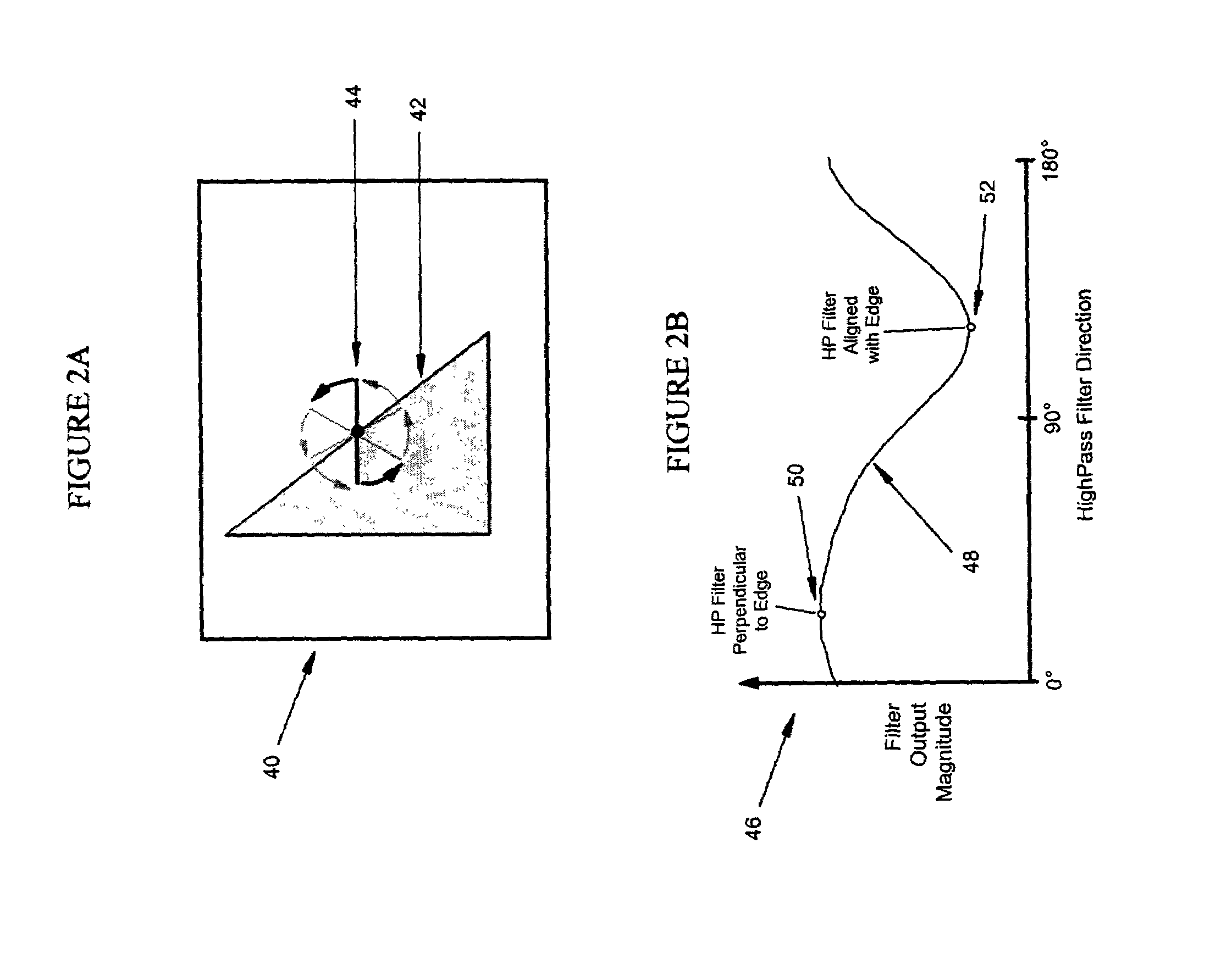
[0033]A method and apparatus for interlace to progressive scan conversion based on the detection of edges in video image features and calculation of new pixels based on data along those edges is disclosed. In the following description, numerous specific details are set forth in order to provide a thorough understanding of the present invention. It will be understood however that the present invention may be practiced without some or all of these specific details. In other instances, well known process operations have not been described in detail in order not to unnecessarily obscure the present invention.

[0034]The present invention improves upon prior art techniques by detecting the presence and orientation of object edges in the image, and, where motion exists, utilizing the edge detection information to compute new pixels based upon pixel data along the object edge. The detection of edges utilizes a novel edge detection technique, different than that used in the prior art, which i...


PUM


Abstract

An interlaced to progressive scan video converter which identifies object edges and directions, and calculates new pixel values based on the edge information. Source image data from a single video field is analyzed to detect object edges and the orientation of those edges. A 2-dimensional array of image elements surrounding each pixel location in the field is high-pass filtered along a number of different rotational vectors, and a null or minimum in the set of filtered data indicates a candidate object edge as well as the direction of that edge. A 2-dimensional array of edge candidates surrounding each pixel location is characterized to invalidate false edges by determining the number of similar and dissimilar edge orientations in the array, and then disqualifying locations which have too many dissimilar or too few similar surrounding edge candidates. The surviving edge candidates are then passed through multiple low-pass and smoothing filters to remove edge detection irregularities and spurious detections, yielding a final edge detection value for each source image pixel location. For pixel locations with a valid edge detection, new pixel data for the progressive output image is calculated by interpolating from source image pixels which are located along the detected edge orientation.

Description

BACKGROUND OF THE INVENTION[0001]1. Field of the Invention[0002]The present invention relates generally to the processing of video images, and more particularly to techniques for deinterlacing video images.[0003]2. Description of the Related Art[0004]The world's major television standards use a raster scanning technique known as “interlacing”. Interlaced scanning draws horizontal scan lines from the top of the screen to the bottom of the screen in two separate passes, one for even numbered scan lines and the other for odd numbered scan lines. Each of these passes is known as a field.[0005]It is often necessary and / or desirable to convert an interlaced video signal to a progressively scanned signal. A single image or frame of a progressively scanned video source is scanned from the top of the screen to the bottom in a single pass. Such a conversion is advantageous, for example, when using a progressive scan display. Many of the display devices used to show interlaced video signals ar...

Claims


Application Information

Patent Timeline
IPC IPC(8): H04N7/01H04N11/20
CPCG06T3/4015G06T7/0083G06T5/20G06T5/002H04N7/0142G06T2207/10016G06T7/12G06T5/70
Inventor ADAMS, DALE R.
Owner LATTICE SEMICON CORP
Learn More