
Decorative glass block and method for making a decorative glass block

a technology of decorative glass and glass blocks, applied in the field can solve the problems of increasing the cost of batch processing, increasing the cost of individual glass blocks modified with such decorations, and affecting so as to enhance the appearance of decorative glass blocks and the aesthetic valu

Inactive Publication Date: 2006-04-04
FERTIG PAMELA E
View PDF17 Cites 26 Cited by
  • Summary
  • Abstract
  • Description
  • Claims
  • Application Information

AI Technical Summary

Benefits of technology

[0006]In general, the present invention contemplates a decorative glass block. The decorative glass block includes a bowl-shaped first half and a bowl-shaped second half joined together. The first half and the second half each include a face, a lip surrounding the perimeter of the face, and an interfacing wall portion extending outwardly from the lip around the perimeter of the face. Decorations are provided on at least one of the faces, and a hole is provided in one of the faces, in one of the wall portions, or along the interface between the wall portions. The decorative glass block is illuminated using a string of lights inserted into the interior of the decorative glass block through the hole. The decorations enhance the appearance of the decorative glass block and the aesthetic value of light transmitted by the decorative glass block when the decorative glass block is illuminated.

Problems solved by technology

However, since standard glass blocks are made in a batch process, it is has been heretofore difficult to modify individual glass blocks with individualized decorations.
Such interruptions would significantly increase the cost of the batch process, and, therefore, increase the cost of individual glass blocks modified with such decorations.

Method used


Image

  • Decorative glass block and method for making a decorative glass block
  • Decorative glass block and method for making a decorative glass block
  • Decorative glass block and method for making a decorative glass block

Examples


Embodiment Construction

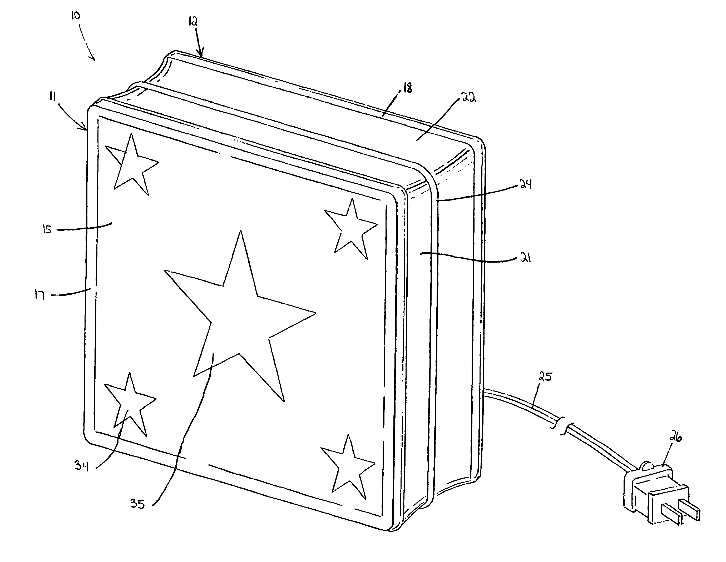
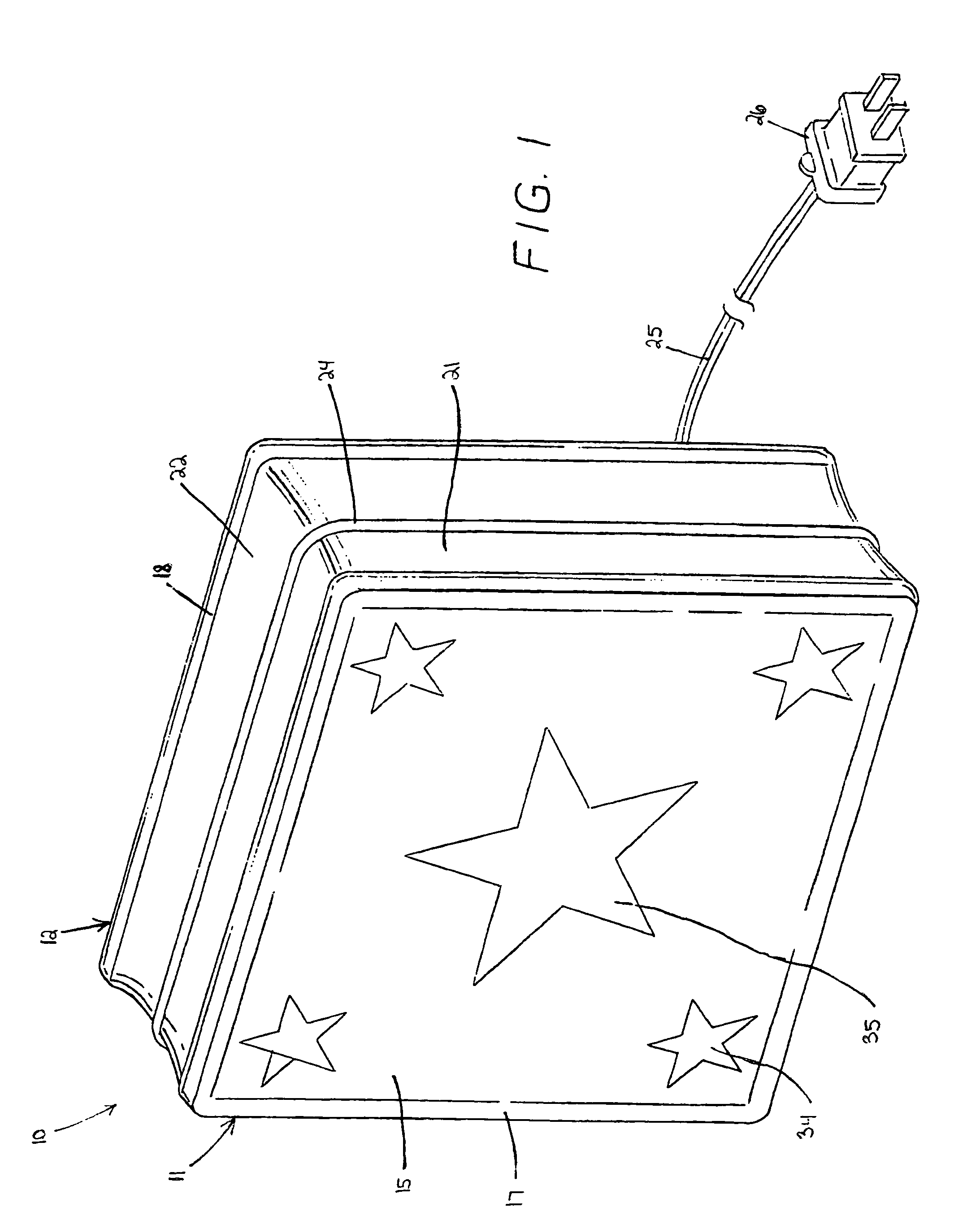
[0014]Referring to FIG. 1, a decorative glass block of the present invention is generally indicated by the numeral 10. The decorative glass block 10 is composed of a first half 11 and a second half 12. The first half 11 and second half 12 are both bowl-shaped, and are mirror images of one another. The decorative glass block 10 is hollow, and the first half 11 and second half 12 enclose an interior area 13.

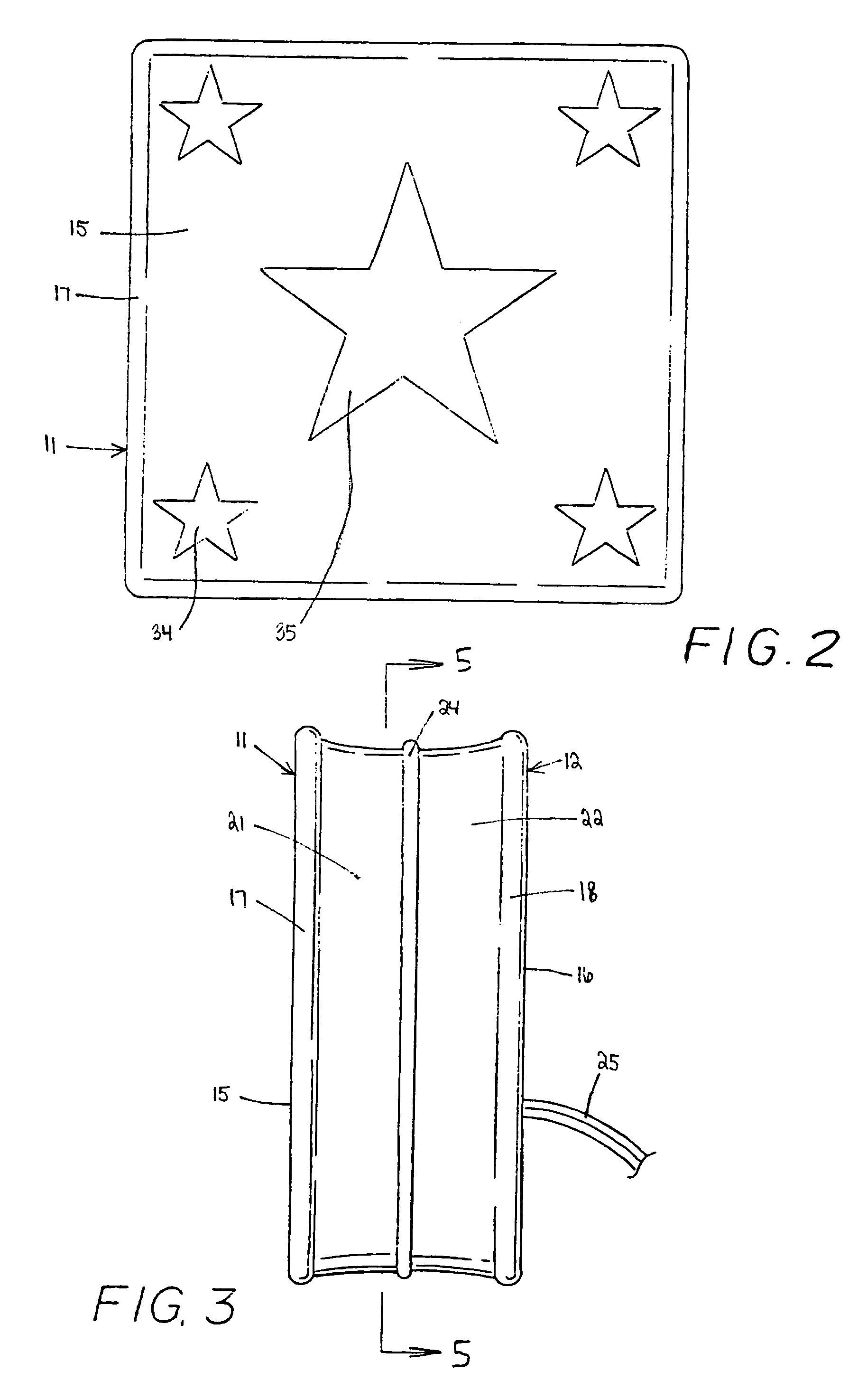
[0015]The first half 11 has a face 15 and the second half 12 has a face 16. A lip 17 surrounds the perimeter of face 15 and a lip 18 surrounds the perimeter of face 16. Extending outwardly from the lip 17 around the perimeter of the face 15 is a wall portion 21. Extending outwardly from the lip 18 around the perimeter of the face 16 is a wall portion 22. The face 15, lip 17, and wall portion 21 form the bowl-shape of the first half 11, and the face 16, lip 18, and wall portion 22 form the bowl-shape of the second half. As seen in FIG. 2, the first half 11 and second half 12 are joi...


PUM

PropertyMeasurementUnit
perimeteraaaaaaaaaa
semi-transparentaaaaaaaaaa
structural strengthaaaaaaaaaa

Abstract

The decorative glass block includes a bowl-shaped first half and a bowl-shaped second half joined together. The first half and the second half each include a face, a lip surrounding the perimeter of the face, and a wall portion extending outwardly from the lip around the perimeter of the face. Decorations including layers of paint, decals, decoupage glaze, and glitter are provided on at least one of the faces. A hole sized to accommodate a string of lights is provided in one of the faces. The decorative glass block is illuminated using a string of lights inserted into the interior of the decorative glass block through the hole. The decorations enhance the appearance of the decorative glass block and the aesthetic value of light transmitted by the decorative glass block when the decorative glass block is illuminated.

Description

RELATED PATENT APPLICATIONS[0001]None.BACKGROUND OF THE INVENTION[0002]This invention relates in general to glass blocks used for decorative purposes, and a method for modifying standard glass blocks to enhance their aesthetic properties.DESCRIPTION OF THE PRIOR ART[0003]It has long been known to use standard glass blocks as building materials. Such standard glass blocks provide a pleasing aesthetic appearance while at the same time providing structural strength and integrity. To allow for the penetration of light, standard glass blocks are generally formed of a transparent glass material. Furthermore, the surface of the transparent glass material is patterned to diffuse light transmitted from one side of the glass block to the other.[0004]However, since standard glass blocks are made in a batch process, it is has been heretofore difficult to modify individual glass blocks with individualized decorations. For example, to modify individual glass blocks, the batch process would have t...

Claims


Application Information

Patent Timeline
Patent Type & Authority Patents(United States)
IPC IPC(8): B32B1/02
CPCE04C1/42F21V33/006G09F13/0413F21S4/001Y10T428/131Y10S362/806Y10T428/24273F21W2121/00F21S4/10
Inventor FERTIG, DWIGHT
Owner FERTIG PAMELA E
Learn More