
Four massaging head type massaging mechanism and massaging apparatus incorporating the same

Active Publication Date: 2006-04-04
DAITO ELECTRIC MACHINE IND
View PDF7 Cites 7 Cited by
  • Summary
  • Abstract
  • Description
  • Claims
  • Application Information

AI Technical Summary

Benefits of technology

[0019]Furthermore, since the swing arm is secured to the first rotary shaft without using any lever in the conventional mechanism, the messaging mechanism of a compact size can be obtained by reducing the overall thickness of the massaging mechanism. At the same time, the number of parts and manufacturing costs can be reduced.
[0023]That is, the second operating mechanism is allowed to move irrespective of the provision of the swing arms to the first rotary shaft, whereby the swing arms are allowed to rotate when the user's body is pressed against the massaging heads. Accordingly, the respective massaging heads can be brought into substantially uniform contact with the user's body, and effective massage can be performed.
[0028]Accordingly, not only the thickness of the massaging mechanism, but also the longitudinal size thereof can be reduced, so that the whole size of the massaging mechanism can be further reduced.
[0030]Accordingly, the lateral width (the width in the right and left direction) of the massaging mechanism can be reduced, and the whole size of the massaging mechanism can be further reduced.
[0041]Further, since the swing arms is provided on the first rotary shaft without any lever, the overall thickness of the massaging mechanism can be reduced, thereby reducing a whole size of the massaging mechanism. At the same time, number of parts and manufacturing costs can be also reduced.

Problems solved by technology

However, this massaging apparatus has a disadvantage that the whole thickness of the massaging mechanism (the depth in the front-and-back direction) is increased by an amount corresponding to the lever because the massaging apparatus is provided with the lever projecting from the rotary shaft toward a front surface side of the backrest.
Since this results in an increase in size and weight of the chair type massaging apparatus, an overall balance of the chair (the relative balance to the seat portion) is lost, and the appearance of the chair may be degraded.
In those examples, the large thickness of the massaging mechanism induces increase in size and weight of the overall massaging apparatus, resulting in an obstacle to portability.
In this case, however, the rotation of the swing arm about the rotary shaft is restrained by the crank rod, thereby hindering all the massaging heads from uniformly contacting a user's back in conformity with the S-shaped curve of the back.
Therefore, since some of the massaging heads cannot contact the user's body at all times or the kneading or tapping force is partially weakened, effective massaging operation cannot be performed.

Method used


Image

  • Four massaging head type massaging mechanism and massaging apparatus incorporating the same
  • Four massaging head type massaging mechanism and massaging apparatus incorporating the same
  • Four massaging head type massaging mechanism and massaging apparatus incorporating the same

Examples


first embodiment

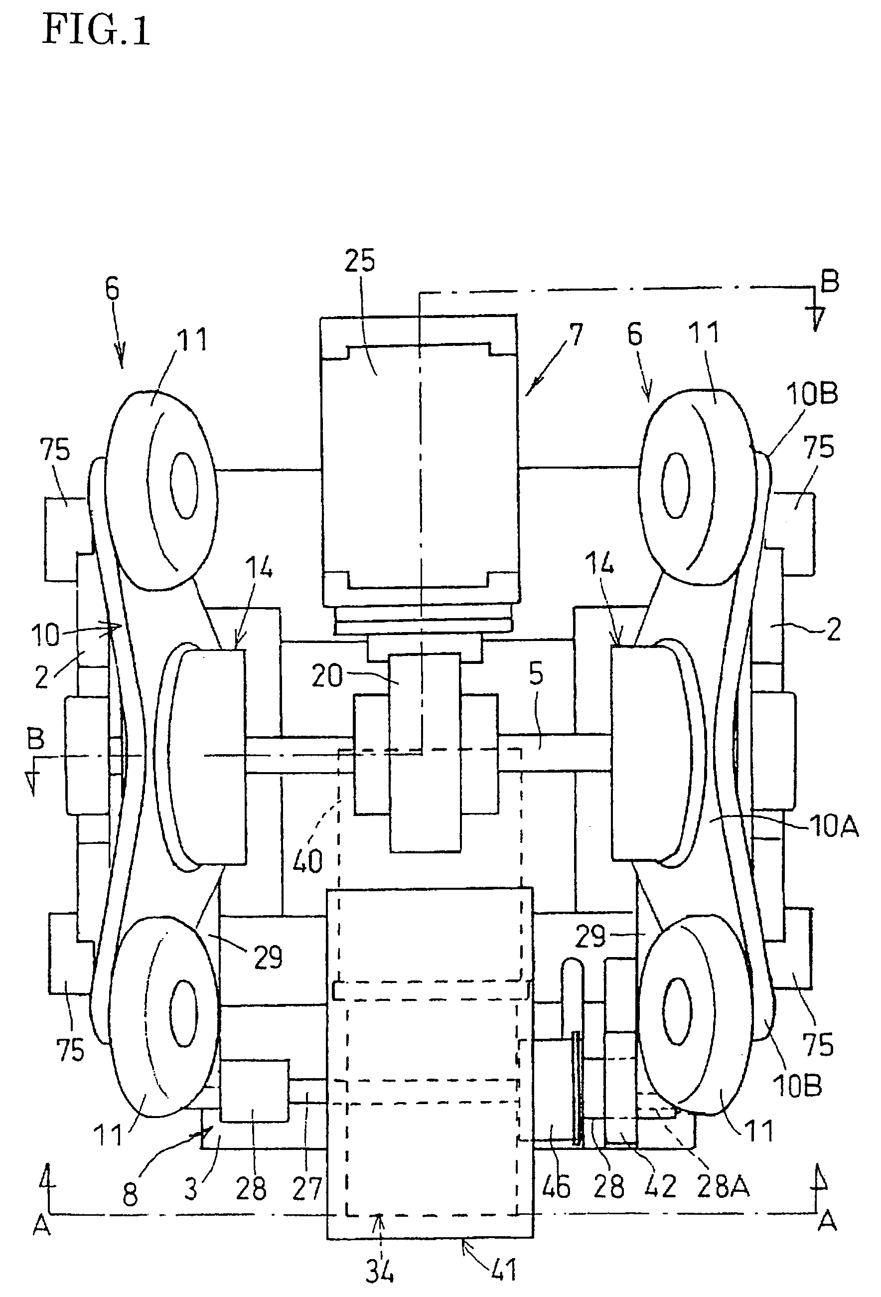
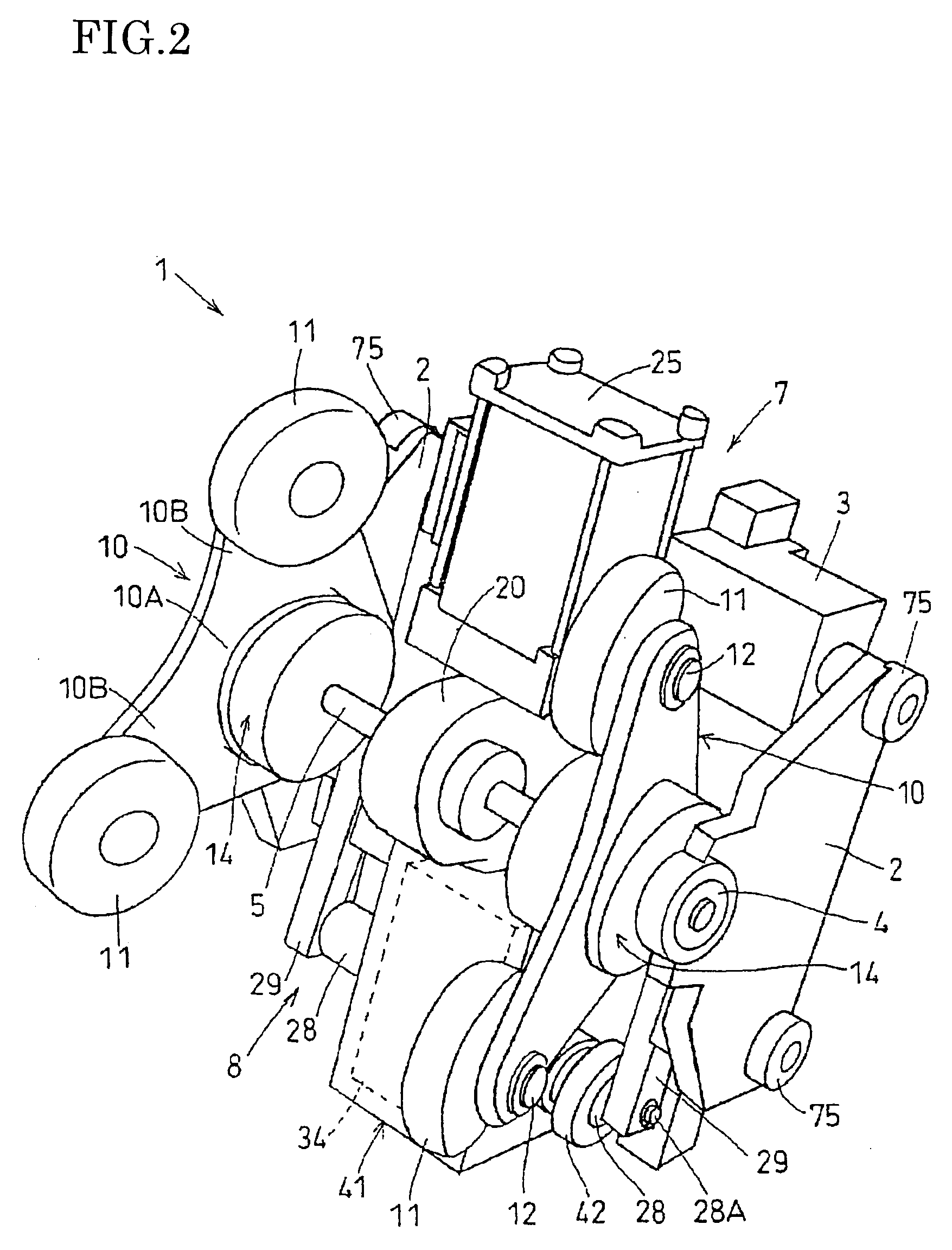
[0070]FIGS. 1 to 11 show the invention.

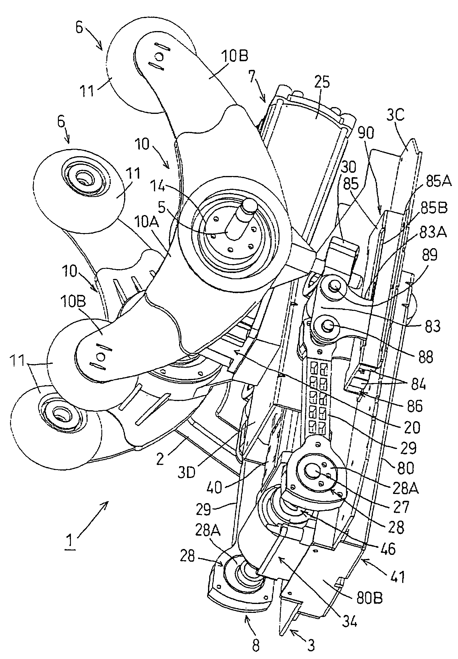
[0071]As shown in FIGS. 1 and 2, a massaging mechanism 1 according to this embodiment of the invention comprises a support frame 3 having right and left support brackets 2 disposed on right and left end portions thereof so as to be spaced from each other at a predetermined interval, a first rotary shaft 5 rotatably supported in the right-and-left direction at opposite end portions thereof through bearings 4,4 by the brackets 2 of the support frame 3, a four massaging head type massaging member 6 disposed on the first rotary shaft 5, a first operating mechanism 7 for causing the massaging member 6 to perform kneading massage and a second operating mechanism 8 for causing the massaging member 6 to perform tapping massage.

[0072]In the following description of the massaging mechanism 1, the right-and-left direction, the up-and-down direction and the sheet penetrating direction in FIG. 1 correspond to the right-and-left direction, the up-and-down di...


PUM


Abstract

A massaging mechanism includes a first rotary shaft supported in a right-and-left direction right and left swing arms relatively rotatably mounted on the first rotary shaft, massaging heads each secured to an upper and a lower end portion of each of the swing arms, a bracing member engaged with each of the swing arms to restrain the swing arm from rotating in connection with rotation of the first rotary shaft, a first operating mechanism for swinging the swing arms in opposite directions in the right-and-left direction to each other so that a right and left pair of massaging heads respectively secured to the upper end portions move toward each other while the massaging heads respectively secured to the lower end portions of the swing arms are moved away from each other in the right-and-left direction, and vice versa, by the rotation of the first rotary shaft.

Description

[0001]This Nonprovisional application claims priority under 35 U.S.C. §119(a) on Patent Application No(s). 2003-054508 filed in JAPAN on Feb. 28, 2003, the entire contents of which are hereby incorporated by reference.BACKGROUND OF THE INVENTION[0002]1. Field of the Invention[0003]The present invention relates to a four massaging head type massaging mechanism for massaging a user's body with four massaging heads which are independent of each other, and massaging apparatus incorporating the massaging mechanism.[0004]2. Description of the Related Art[0005]Massaging apparatus in which a four massaging head type massaging mechanism for massaging a user's body with four independent massaging heads is installed in a backrest is known particularly in the technical field of chair type massaging apparatus. The massaging mechanism concerned has a rotary shaft supported in the right-and-left direction, a pair of right and left swing arms which are interlockingly linked to the rotary shaft so t...

Claims


Application Information

Patent Timeline
IPC IPC(8): A61H15/00A61H1/00
CPCA61H15/00A61H7/007A61H15/0078A61H2015/0028A61H2201/0138A61H2201/0149A61H2205/081A61H2201/1427A61H2201/1623A61H2201/1654A61H2201/1669
Inventor SHIMIZU, NOBUZOSHIRAISHI, SATORULV, SHU
Owner DAITO ELECTRIC MACHINE IND
Learn More