Video processing device
a video processing and video technology, applied in the field of video processing devices, can solve the problems of increasing the error rate of digital video information, unable to correct the error of audio information, and unable to solve the error of video information, etc., to achieve the effect of less scanning lines, small error rate and lower horizontal resolution
- Summary
- Abstract
- Description
- Claims
- Application Information
AI Technical Summary
Benefits of technology
Problems solved by technology
Method used
Image
Examples
first embodiment
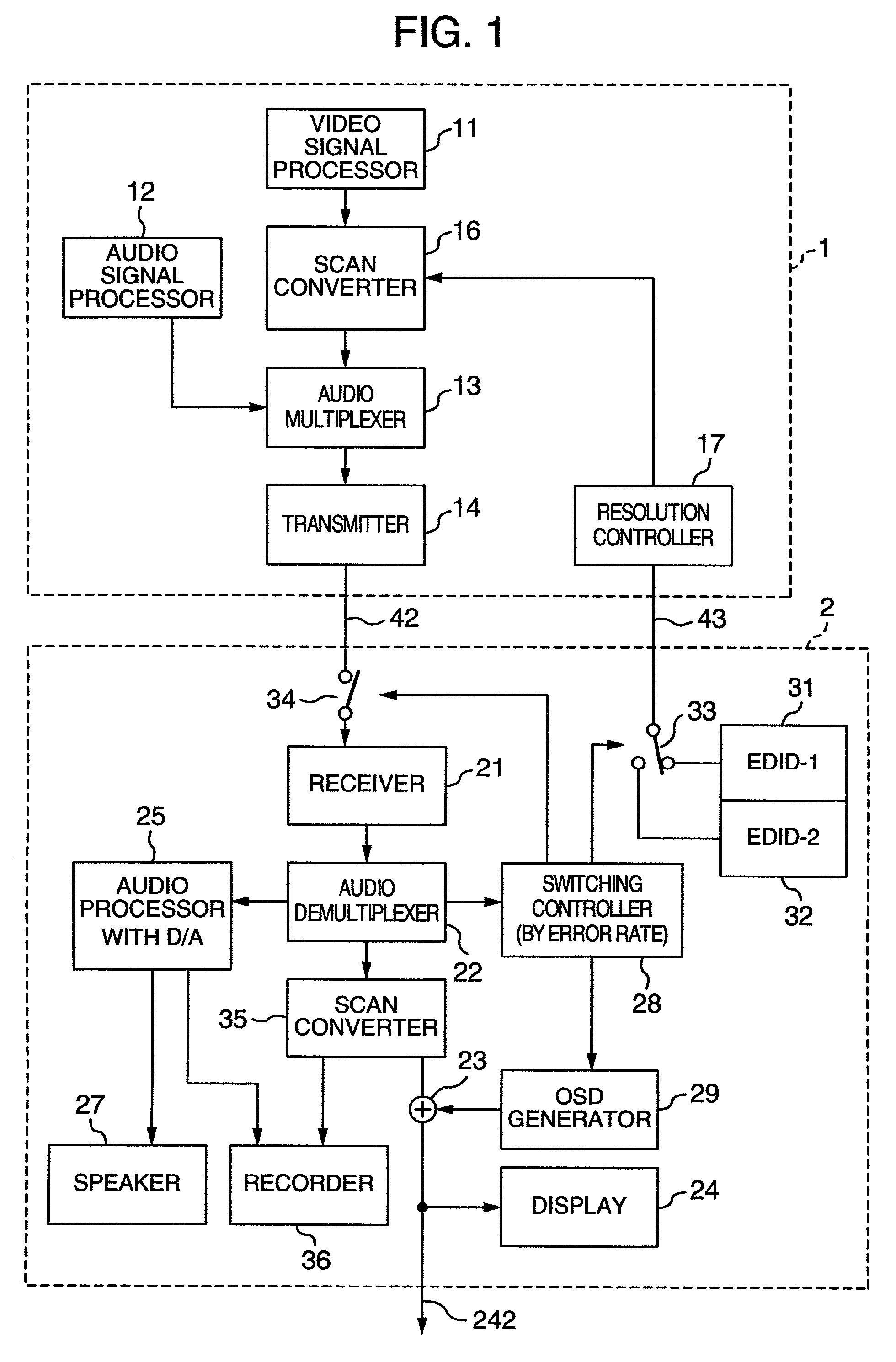
[0027]An operation for the above processing will be described with reference to FIG. 1 with special emphasis on the items mentioned above. FIG. 1 is a block diagram showing the invention and it is provided with a signal generating device 1 such as an STB and a video processing device 2. Here, the video processing device 2 will be described referring to a display device such as a television receiver. They are mutually connected through two interfaces (cables or the like) 42, 43. In this embodiment, the signal generating device 1 and the video processing device 2 are connected through the two interfaces, but they may be connected though a single interface when such communications functions can be made by a single interface.
[0028]First, details of the signal generating device 1 will be described. A digital video signal is generated from a video signal source 11 of the signal generating device 1, and a digital audio signal is generated from an audio signal processor 12. When the signal ...
second embodiment
[0051]Then, the invention will be described with reference to the block diagram of FIG. 5. Here, an interface of video information between the signal generating device 1 and the display device 2 is performed by two systems of digital and analog, and a preferable one (in terms of image quality) is selected for displaying.
[0052]In FIG. 5, like reference numerals are used to indicate like components as those shown in FIG. 1. Components related to the transmission of an audio signal are omitted. In the signal generating device 1, the video signal generated by the digital video signal source 11 is divided into two systems. One of the divided signals is supplied to the video processing device 2 which is a display device in a digital form via a first scan converter 161, a digital transmitter 142 and then the interface 42. The other is supplied to the video processing device 2 through an interface 41 as an analog form video signal after passing through a second scan converter 162 and a DAC ...
third embodiment
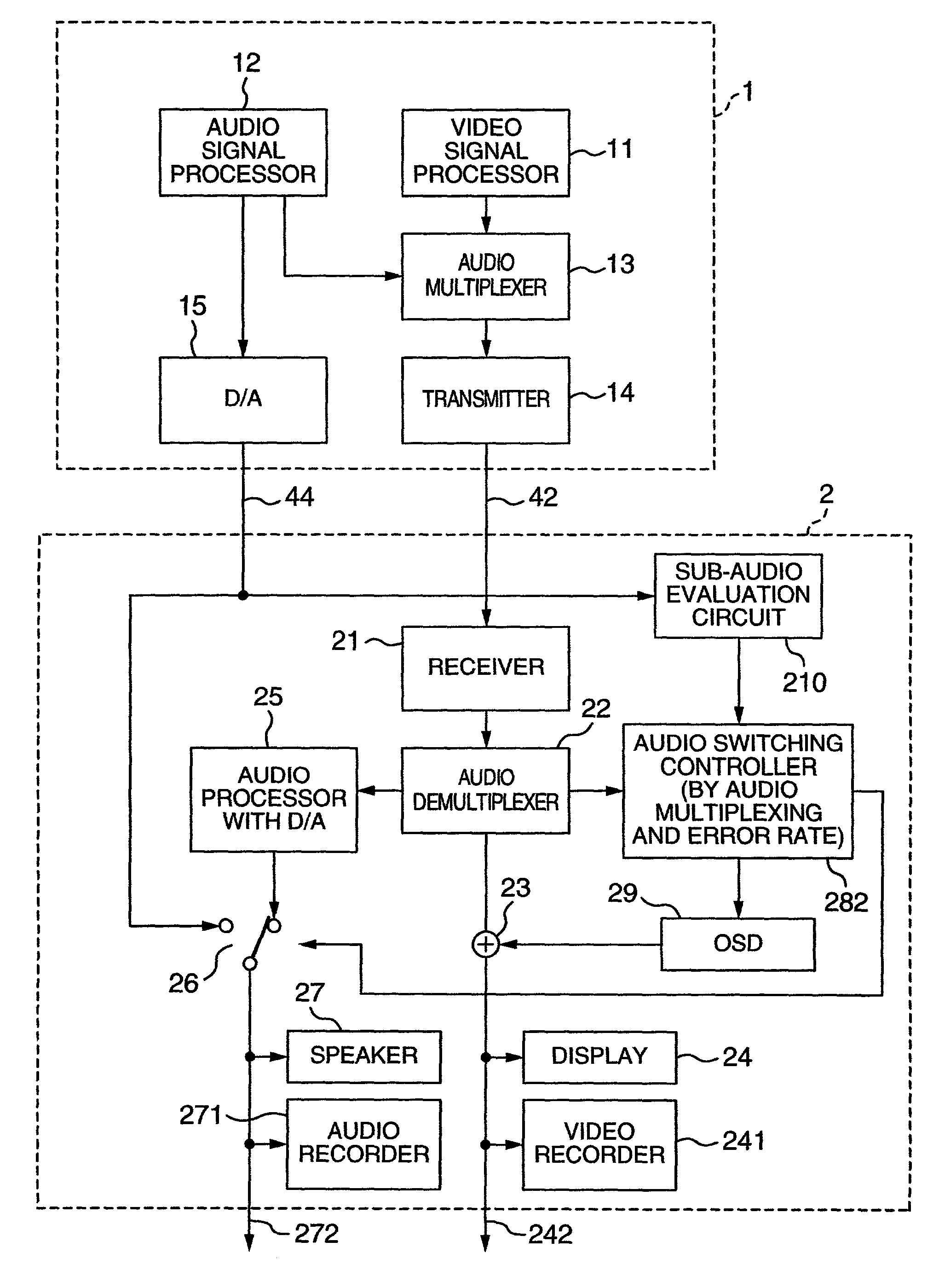
[0061]Then, the invention will be described with reference to the block diagram of FIG. 6. Here, when two systems of digital audio and analog audio are being sent, one with desirable sound quality is selected and reproduced.
[0062]In FIG. 6, like reference numerals are used for like components as those shown in FIG. 1. In the signal generating device 1, the digital audio signal generated by the digital audio signal processor 12 is divided into two systems, and one of them is passed through the audio multiplexer 13, where the digital sound is superimposed on the digital video signal, and the digital transmitter 14 so to be supplied to the video processing device 2, which is a display device, through the interface 42. The other is passed through the DAC so to be changed to an analog audio signal and supplied to the video processing device 2 through the interface 44.
[0063]In the display device 2, an audio switching controller 282 decides which of the analog audio or the digital audio is...
PUM
 Abstract
Description
Claims
Application Information
 - R&D
- Intellectual Property
- Life Sciences
- Materials
- Tech Scout
- Unparalleled Data Quality
- Higher Quality Content
- 60% Fewer Hallucinations
Browse by: Latest US Patents, China's latest patents, Technical Efficacy Thesaurus, Application Domain, Technology Topic, Popular Technical Reports.
© 2025 PatSnap. All rights reserved.Legal|Privacy policy|Modern Slavery Act Transparency Statement|Sitemap|About US| Contact US: help@patsnap.com


