Eureka AIR delivers breakthrough ideas for toughest innovation challenges, trusted by R&D personnel around the world.

Circuit for sensing on-die temperature at multiple locations

a technology of circuits and dies, applied in the direction of heat measurement, instruments, pulse techniques, etc., can solve the problems of reducing performance and even failure, difficult to directly measure the temperature at the active part of the die using a thermocouple or other external measuring device, and often a distance from the diod

Inactive Publication Date: 2006-03-28
INTEL CORP
View PDF20 Cites 13 Cited by
  • Summary
  • Abstract
  • Description
  • Claims
  • Application Information

AI Technical Summary

Benefits of technology

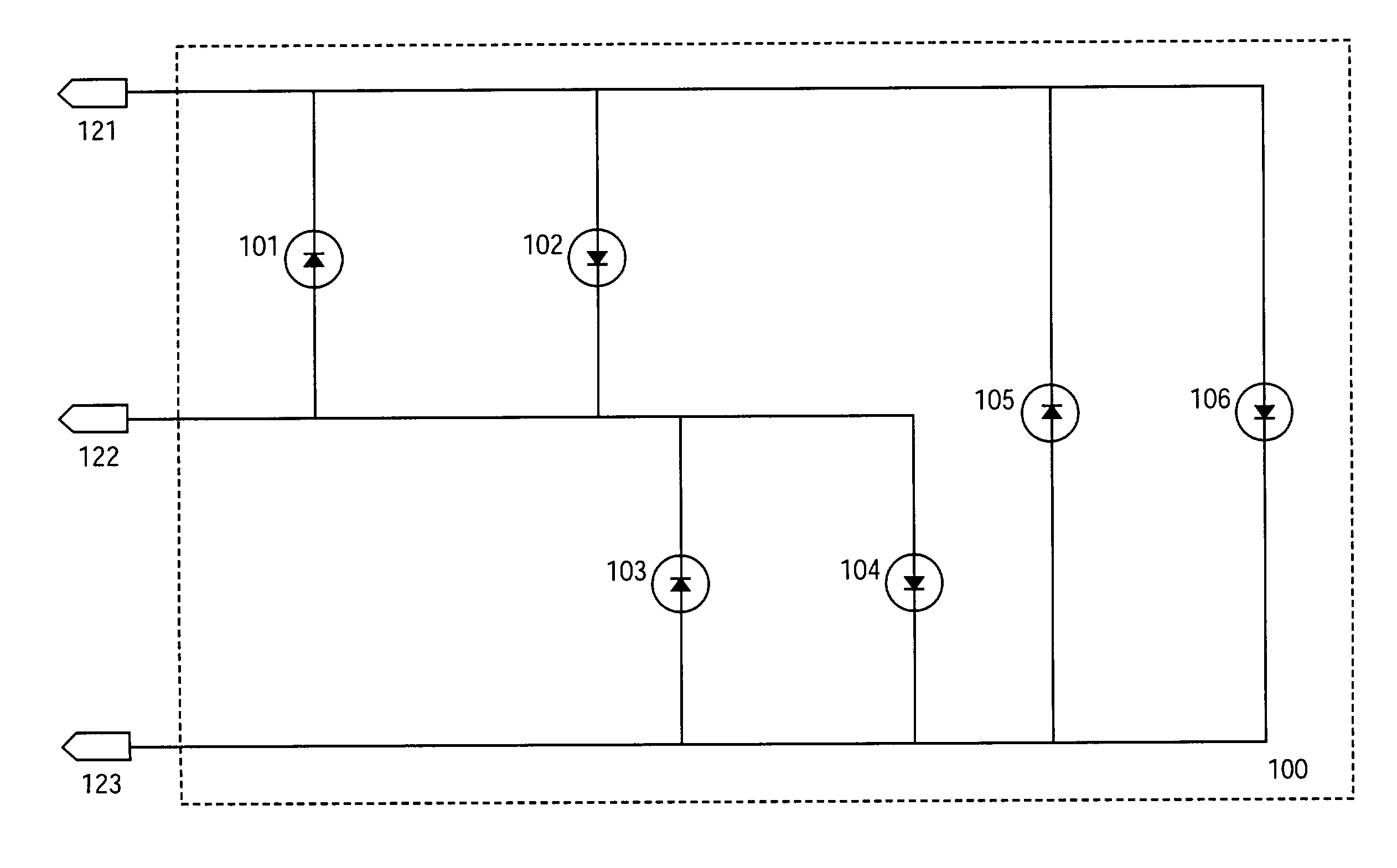
The present invention relates to a circuit for sensing the temperature of an integrated circuit (IC) at multiple locations using a minimum number of integrated circuit (IC) terminals. The circuit allows for the placement of multiple thermal diodes on the die while minimizing the number of IC terminals used. The use of multiple thermal diodes allows for the determination of thermal gradients on the IC. The circuit uses the electrical properties of diodes to measure temperature. The technical effect of the invention is to provide a more efficient and accurate method for measuring the temperature of an IC.

Problems solved by technology

An overheated IC can potentially result in reduced performance and even failure.
ICs, however, are typically packaged in such a way that it is difficult to directly measure the temperature at the active part of the die using a thermocouple or other external measuring device.
In reality, however, the diode is often a distance from the IC terminals due to area constraints.
In addition, as the trend in IC design continues toward smaller chips, the power density increases and becomes less uniform.
Because IC terminals are at a premium on chips, the addition of thermal diodes beyond the first one may be cost prohibitive.

Method used


Image

  • Circuit for sensing on-die temperature at multiple locations
  • Circuit for sensing on-die temperature at multiple locations
  • Circuit for sensing on-die temperature at multiple locations

Examples


Embodiment Construction

[0014]In the following detailed description, numerous specific details are set forth in order to provide a thorough understanding of the invention. However, it will be understood by those skilled in the art that the present invention may be practiced without these specific details. In other instances, well-known methods, procedures, components and circuits have not been described in detail so as not to obscure the present invention.

[0015]The use of multiple thermal diodes allow for the determination of thermal gradients on an IC. Multiple diodes may be used to measure die temperature without having to use two times the number of IC terminals per diode by taking advantage of the diodes' electrical properties. A diode has an anode terminal and a cathode terminal. Current flows primarily from the anode terminal of the diode to the cathode terminal.

[0016]Therefore, if two diodes having opposite polarity (terminals are flipped with respect to one another) are placed between two parallel ...


PUM

PropertyMeasurementUnit
temperatureaaaaaaaaaa
voltageaaaaaaaaaa
polarityaaaaaaaaaa

Abstract

A circuit for sensing on-die temperature at multiple locations using a minimum number of pins is described. Thermal diodes coupled to pins are placed on a die to measure the temperature at various die locations. Voltage is applied to the pins to determine the temperature at each given diode location. The polarity of the voltage applied across the pins determines what diodes are selected for measurement.

Description

FIELD OF THE INVENTION[0001]The present invention pertains to the field of integrated circuit design. More particularly, the present invention relates to a circuit for sensing temperature at multiple locations on a silicon die using a minimum number of integrated circuit terminals.BACKGROUND OF THE INVENTION[0002]An integrated circuit (IC) is a device consisting of a number of connected circuit elements, such as transistors and resistors, fabricated on a single chip of silicon crystal or other semiconductor material. During operation, an IC burns power causing the temperature of the IC to increase. An overheated IC can potentially result in reduced performance and even failure.[0003]ICs, however, are typically packaged in such a way that it is difficult to directly measure the temperature at the active part of the die using a thermocouple or other external measuring device. As a result, the standard method for measuring the die temperature of an IC is to incorporate a thermal diode ...

Claims


Application Information

Patent Timeline
Patent Type & Authority Patents(United States)
IPC IPC(8): G01K13/00G06F1/32G01K7/01
CPCG01K7/01
Inventor GRANNES, DEAN J.SINGH, HARJINDERGAYMAN, JASON A.
Owner INTEL CORP
Why Eureka
Eureka Blog
Learn More