
Rubber cylinder sleeve for offset presses

a technology of offset presses and rubber cylinders, which is applied in the direction of mounting boards, printing, printing, etc., can solve the problems of increasing the length-to-thickness ratio of printing cylinders, the shape and position of printing cylinders with respect to one another changing in an undesired manner, and the formation of folds, so as to influence the conveying characteristics of rubber cylinders without affecting the radial compressibility or radial rigidity over the sleev

Inactive Publication Date: 2006-03-21
MANROLANAD AG
View PDF12 Cites 0 Cited by
  • Summary
  • Abstract
  • Description
  • Claims
  • Application Information

AI Technical Summary

Benefits of technology

[0012]It is an object of the present invention to develop a rubber cylinder sleeve of the type described in the introduction so that quality assurance in rotary printing is possible, in which it is possible to influence the conveying characteristics of the rubber sleeve without impairing the radial compressibility or the radial rigidity over the sleeve length.
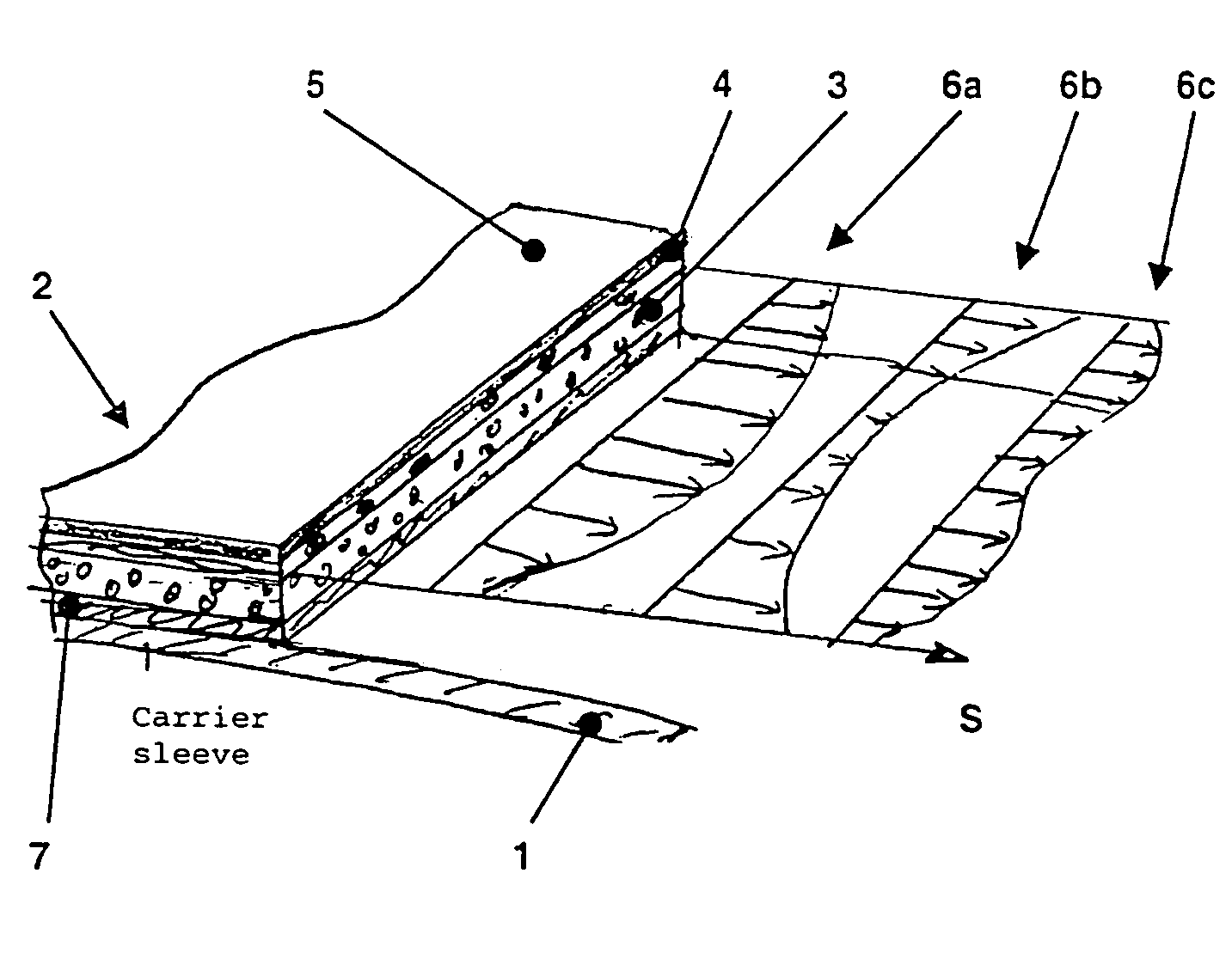
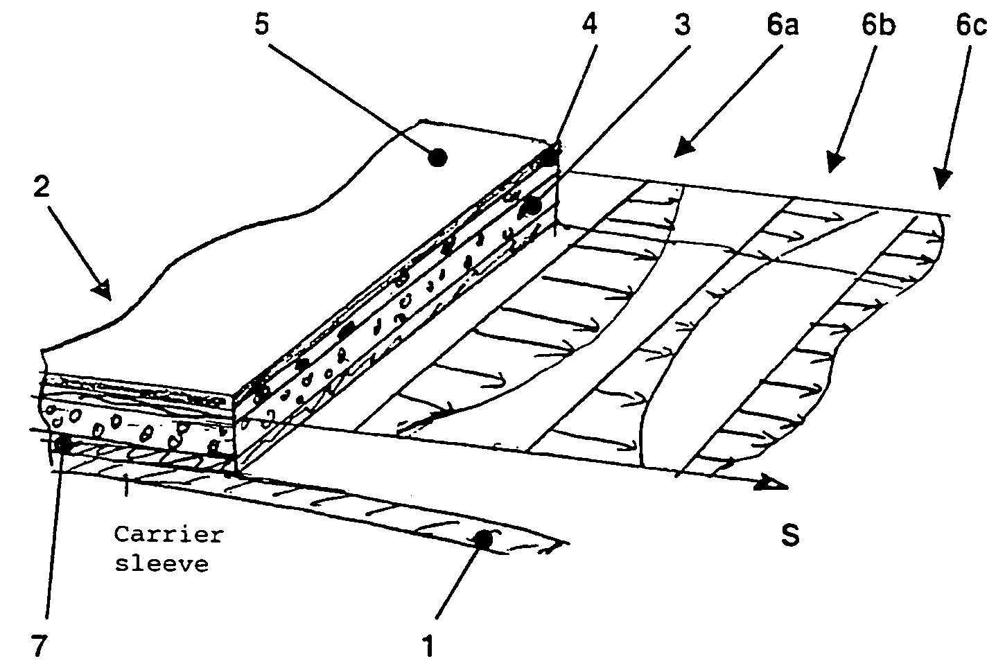
[0014]By virtue of the fact that, according to the invention, the stiffness of a rubber sleeve is modified across the web width and is not impaired in the circumferential direction, it is firstly possible to influence the conveying characteristics across the paper-web width without, however, impairing the compressibility of the rubber sleeve.

Problems solved by technology

Here, a problem arises for quality assurance from the demand for ever higher productivity, and as a result of the efforts to produce impression cylinders which are as light and cost-effective as possible.
As a result, the length-to-thickness ratio of the printing cylinders, or their relative rigidity with regard to deflection, becomes ever more unfavorable.
The consequence of this is that, during printing operation, the shape and position of the printing cylinders with respect to one another change in an undesired manner, i.e. the printing cylinders are deflected.
As a result of the mechanical misalignment remaining with this, it is known that folds can form in the conveyed paper web in the press nip of the rubber cylinder if the paper web is moving here with an irregular speed profile across the width because of the above-described positional change, the center of the paper web moving more quickly than the outside of the web, which leads to the formation of folds.
In sleeve presses, in particular, it is the case that folds may form across the web width, which impair the page register.
Although the deflection between a blanket cylinder and a plate or forme cylinder can be compensated for by a convex profile of the blanket-cylinder surface, the contact is impaired, on the other hand, between the two blanket cylinders in a printing unit for recto and verso printing.
This has a negative influence on both the web transport and the ink transfer to the paper web.
Although the contact between the two blanket cylinders in the press nip is improved by a concave blanket-cylinder surface, the ink transfer from the plate or forme cylinder to the blanket cylinder is then impaired.
Moreover, the above-described measures to influence the conveying characteristics have the disadvantage that the radial compressibility or radial rigidity is modified over the sleeve length, which in turn impairs the print quality, in particular the tonal value gain.

Method used


Image

  • Rubber cylinder sleeve for offset presses
  • Rubber cylinder sleeve for offset presses

Examples


Embodiment Construction

[0018]The rubber cylinder sleeve comprises an inner carrier sleeve 1 which can be expanded using air and to which a rubber covering 2 is fixed, which comprises a plurality of layers 3, 4, 5. In the exemplary embodiment, the carrier sleeve 1 is composed of a metal, for example of steel, and is produced from a plate, the ends of which are welded together, so that a butt joint is produced. It is, however, also possible to configure the carrier sleeve 1 to be endless, that is to say without a butt joint, produced, for example, galvanically from nickel. It is also possible for the carrier sleeve 1 to be composed of a plastic, for example of a fiber-reinforced epoxy resin, for example CRP. In all cases, it is possible to expand the carrier sleeve 1 elastically by means of compressed air and to push it in this way axially onto a printing-unit cylinder.

[0019]The layer construction 2 is usually vulcanized or adhesively bonded onto the carrier sleeve 1, forming an adhesive layer 7, butt joint...


PUM


Abstract

A rubber cylinder sleeve has a rubber covering with a layer construction which includes, at a distance from the outer surface, compressible layer elements and layer elements which influence the stiffness (S), such as filaments / yarns or fabric structures. The layer elements which influence the stiffness (S), are incorporated uniformly in the circumferential direction but are prestrained to various degrees in a defined manner in the direction of the sleeve axis, so that a stiffness profile is produced across the sleeve width, which profile is symmetrical with respect to the center of the sleeve width.

Description

BACKGROUND OF THE INVENTION[0001]1. Field of the Invention[0002]The invention relates to a rubber cylinder sleeve of the type having a carrier sleeve which can be expanded using air and a rubber covering on the carrier sleeve.[0003]2. Description of the Related Art[0004]Rubber cylinder sleeves are known in which a carrier sleeve is provided with a rubber covering, the rubber covering comprising three or more layers. EP 0 421 145 B1 is to be cited here by way of example.[0005]In rotary offset presses, as is known, the printing image is transferred from the plate or forme cylinder onto the rubber cylinder and from the latter onto the paper running over the impression cylinder. It is only possible to transfer the ink, both from the printing forme onto the rubber sleeve and from the rubber sleeve onto the paper, if a certain minimum pressure is present, what is known as the line pressure between the blanket cylinder and plate or forme cylinder or impression cylinder.[0006]Here, a proble...

Claims


Application Information

Patent Timeline
Patent Type & Authority Patents(United States)
IPC IPC(8): B41F13/10B41N10/04
CPCB41N6/00B41N10/04B41N2210/14B41N2210/04Y10S428/909
Inventor HOFFMANN, EDUARDSAMEIT, CHRISTIANSCHMID, GEORG
Owner MANROLANAD AG
Learn More