
Molded plastic part

a technology parts, applied in the field of molded plastic parts, can solve the problems of ineffective or universal measures, affecting and affecting the performance of molded parts, so as to achieve the effect of not impairing the rigidity of reinforcing structures

Active Publication Date: 2014-05-06
SUZUKI MOTOR CORP
View PDF14 Cites 0 Cited by
  • Summary
  • Abstract
  • Description
  • Claims
  • Application Information

AI Technical Summary

Benefits of technology

[0017]The present invention has been made in view of the above circumstances. Accordingly, it is an object of the present invention to provide a molded plastic part that can prevent an appearance defect such as a flow mark, weld line, or dent occurring on the design surface side of a molded part body constituting a design surface without impairing the rigidity of a reinforcing structure part provided on the back surface of the molded part body and the function of a mounting means, and that is suitable for unpainted resin molding using a colored resin, especially for the injection molding in which a bright material is added to the colored resin.
[0019]With the above-described configuration, the molded plastic part is made such that while the rigidity of a reinforcing structure part is secured by the plurality of transverse ribs and the longitudinal rib, a reinforcing structure part such as a rib extending along the inflow direction of resin is absent on the design back surface so that a weld line occurring on the design surface side of the molded part body can be prevented, and also resin flows into the body part through the transverse rib on which the gate part is set at the time of injection molding, and at this time, the resin flows dividedly from the transverse rib to the longitudinal rib, whereby the inflow velocity is decreased. Therefore, the resin does not arrive at the design surface in a jet state, so that an appearance defect such as a flow mark or a dent can be prevented. For this reason, the molded plastic part in accordance with the present invention is best suitable for unpainted resin molding using a colored resin, especially for injection molding in which a bright material is added to the colored resin.
[0020]Also, in a mode in which the transverse rib on which the gate part is set has a wall thickness larger than that of any of other transverse ribs, the inflow velocity of resin flowing in through the transverse rib on which the gate part is set is further decreased, so that the jet state does not appear, whereby the occurrence of a flow mark can be prevented surely. Further, in a mode in which the transverse rib on which the gate part is set has a fillet part expanding to the design back surface side provided in a portion in which the transverse rib connects with the design back surface, when the resin flows into the body part through the transverse rib on which the gate part is set at the time of injection molding, the inflow velocity of resin is decreased, so that the occurrence of a flow mark on the design surface of the body part can be prevented surely.
[0021]In a mode in which the wall thickness of the longitudinal rib is smaller than the wall thickness of the body part, and the interval between the transverse rib on which the gate part is set and the adjacent transverse rib is greater than any of the intervals between the transverse ribs on which the gate part is not set, the resin flowing into the body part from one of the transverse ribs advances earlier than the resin flowing into the longitudinal rib from the transverse rib, by which the resin is restrained from flowing into the body part from the transverse rib through other transverse ribs. Therefore, the occurrence of a weld line caused by the joining of resins on the design surface is prevented.
[0022]Therefore, in a mode in which a joining location where the resin which flows in from one of the transverse ribs through the body part and solidifies and the resin which flows in from one of the transverse ribs through the longitudinal rib and solidifies join lies in the reinforcing structure part, the occurrence of a weld line and an appearance defect caused by the weld line are prevented surely, so that a high-quality molded plastic part can be obtained.
[0023]Due to the above features, the present invention is best suited for a molded plastic part used as a covering member or a decorative member for an article surface, such as a cover or a garnish, which is light in weight and can be manufactured cheaply.

Problems solved by technology

In the portion in which these structure parts (hereinafter referred inclusively to as a reinforcing structure part) are formed, the fill of resin is greater than that in other portions, so that a molding defect such as a weld line or a dent is liable to occur on the design surface.
However, it is difficult for these measures to be taken for a part in which the whole of design surface is arranged at a conspicuous position, and additionally, if the thickness of the connecting part is made small, a decrease in strength caused by stress concentration is inevitable.
Therefore, these measures are not effective or universal.
However, in recent years, from the viewpoint of environmental protection, in a situation where a demand for reducing environmental pollutants emitted in the manufacturing process increases, there is the risk that volatile organic compounds contained in general paints are released into the atmosphere and adversely impact the environment.
However, an injection molding process using a bright material has the problem that the flow state of the resin in the mold at the time of molding tends to appear on the design surface after molding.
Therefore, if the flow of resin at the time of injection molding is uneven, a portion having a different color tone is produced, which is recognized as an appearance defect.
Although these defects also occur in the case of general resin materials other than colored resins, they especially appear on injection molded components manufactured by using the colored resin, and the number of cases recognized as an appearance defect increases.
In this case, however, after the gate has been separated from the molded component, the cut surface is conspicuous, so that in many molded plastic parts, this type of gate cannot be used from the viewpoint of product appearance.

Method used


Image

  • Molded plastic part
  • Molded plastic part
  • Molded plastic part

Examples


Embodiment Construction

[0033]The present invention will now be described in detail with reference to the following embodiment.

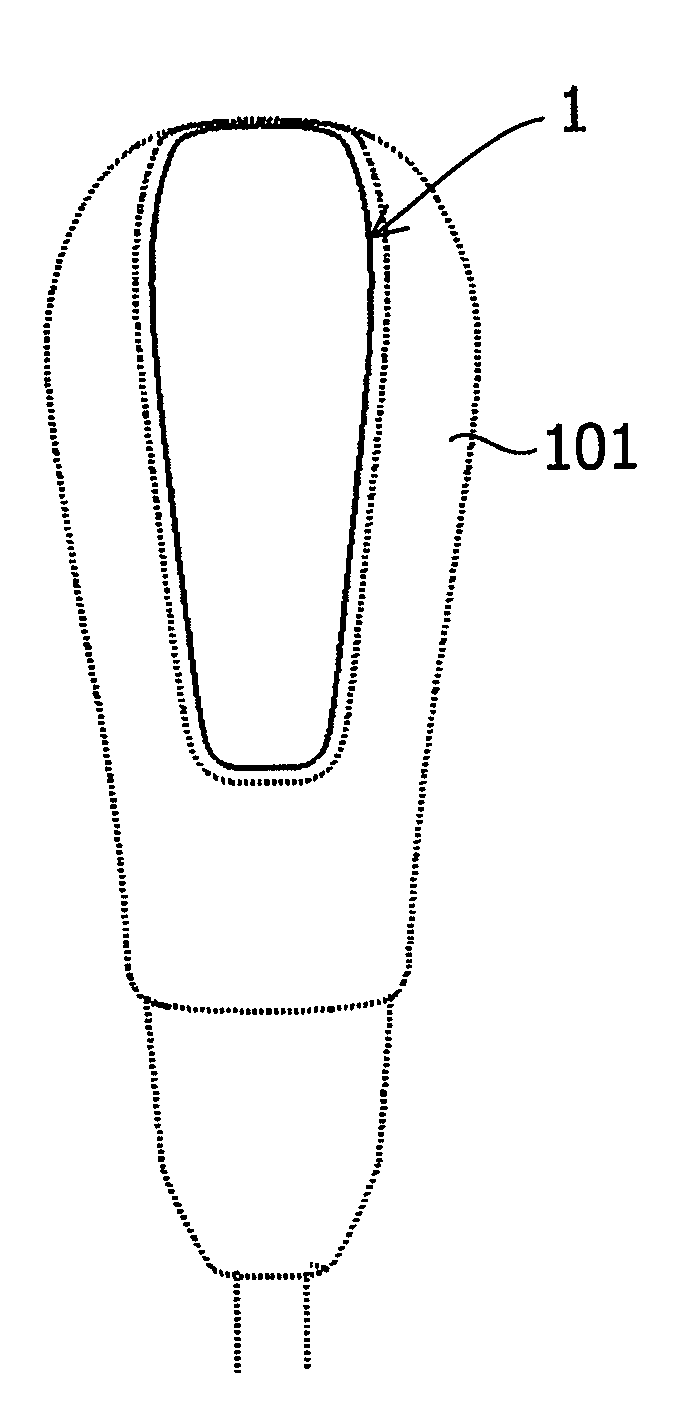
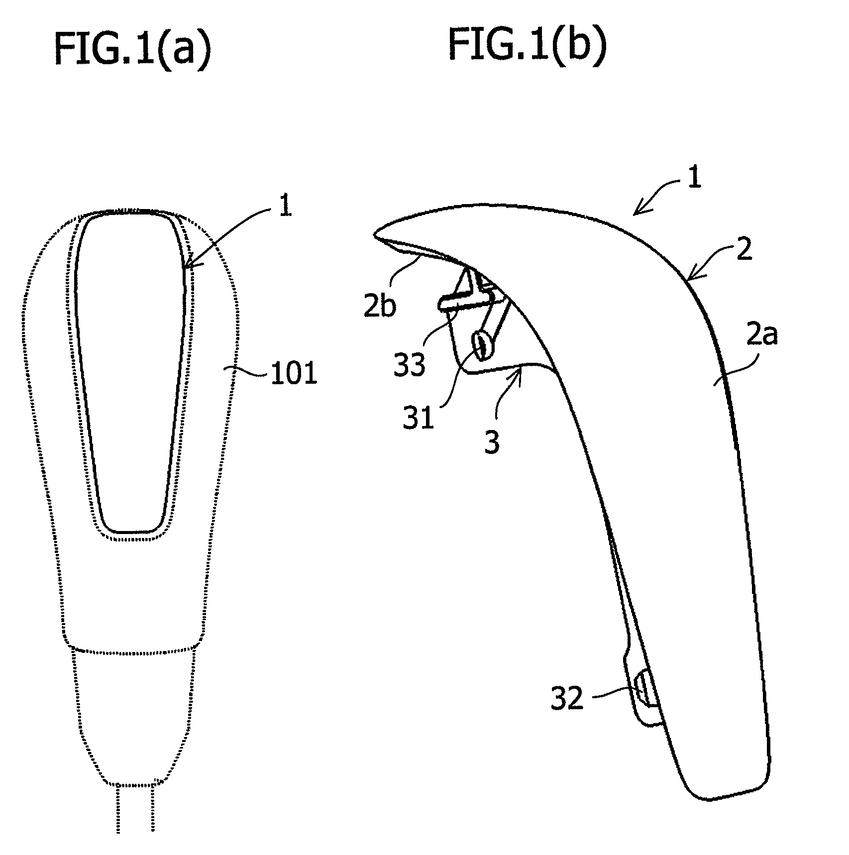
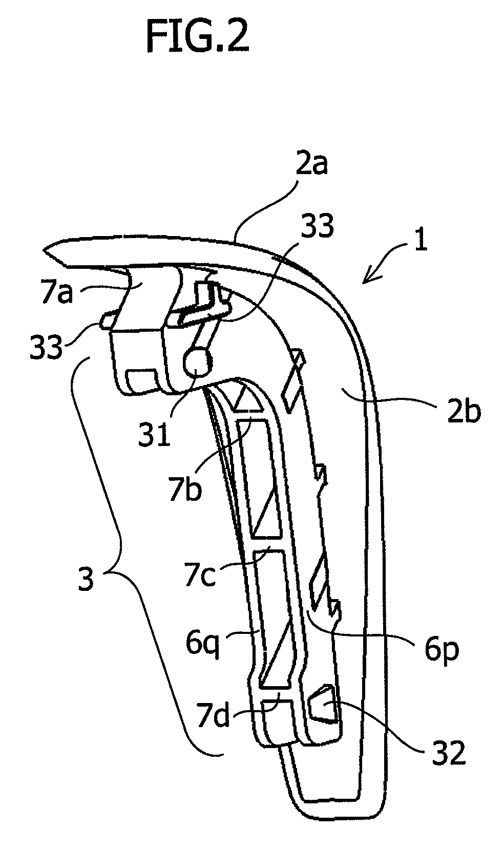
[0034]FIG. 1A shows an automotive shift lever knob 101. In FIG. 1A, the shift lever knob 101 is mounted with a shift lever knob garnish 1 of a molded plastic part constituting a decorative body. As shown in FIG. 1B and FIGS. 2 to 4, the shift lever knob garnish 1 is a molded plastic part in which a body part 2 constituting a design surface 2a and a reinforcing structure part 3 projectingly provided on a design back surface 2b are integrally molded by injection molding using a colored resin. The body part 2 and the reinforcing structure part 3 are curved along the curved surface shape of the shift lever knob 101.

[0035]The reinforcing structure part 3 is formed by a combined body of four transverse ribs 7a, 7b, 7c and 7d arranged in the direction intersecting with the lengthwise direction of the body part 2, namely, in the width direction and two longitudinal ribs 6p and 6q that exte...


PUM

PropertyMeasurementUnit
thicknesses Tpaaaaaaaaaa
thicknesses Tbaaaaaaaaaa

Abstract

In a molded plastic part 1 including a body 2 constituting a design surface 2a and a reinforcing structure 3 projectingly provided on a design back surface 2b of the body 2, the body 2 and the reinforcing structure 3 being integrally molded by injection molding, the reinforcing structure 3 is formed by a combined body of a plurality of transverse ribs 7a, 7b, 7c and 7d which are arranged at appropriate intervals in the resin flow direction at the time of injection molding in the direction intersecting with the resin flow and longitudinal ribs 6p and 6q which extend at right angles to the transverse ribs and connect the transverse ribs to each other. The transverse ribs are connected to the design back surface 2b, and a gate 8 for injection molding is set on one of the transverse ribs. The longitudinal ribs are disposed so as to be separated from the design back surface 2b.

Description

CROSS-REFERENCE TO RELATED APPLICATIONS[0001]This application claims priority from Japanese Application No. 2006-230411, filed Aug. 28, 2006, which is hereby incorporated herein by reference.FIELD OF THE INVENTION[0002]The present invention relates to a molded plastic part integrally molded by injection molding. More particularly, it relates to a molded plastic part that includes a body constituting a design surface and a reinforcing structure projectingly provided on a design back surface of the body, and is mounted to a mounting portion by using the reinforcing structure to cover or decorate the mounting portion by means of the body, and also relates to a molded plastic part suitable for an unpainted molded plastic part, which can prevent an appearance defect such as a flow mark, welding line, or dent (sink mark) from occurring on the design surface.BACKGROUND OF THE INVENTION[0003]Molded plastic parts manufactured by injection molding have widely been used as interior and exterio...

Claims


Application Information

Patent Timeline
Patent Type & Authority Patents(United States)
IPC IPC(8): B32B3/10
CPCF16H59/0278B29L2031/3029B29C2045/0027B29C45/0046B62D29/004F16H59/02B29C45/0025Y10T74/19623Y10T428/1352Y10T74/19967Y10T428/1397Y10T428/24355Y10T74/19907Y10T74/19633Y10T74/19898
Inventor SHINOHARA, RYUTAROUEBAYASHI, HISASHIGE
Owner SUZUKI MOTOR CORP
Learn More