Microfluidic devices for rotational manipulation of the fluidic interface between multiple flow streams

a technology of fluidic interface and microfluidic device, which is applied in the direction of flow mixer, fluid speed measurement, optical light guide, etc., can solve the problems of not being able to achieve a low flow rate with a practical pumping system, several potentially prohibitive restrictions for increasing the time interval, and not being able to image in the x-direction (through the two streams and the interdiffusion region) without the use of more sophisticated equipment. , to achieve the effect o

Inactive Publication Date: 2006-03-14
UNIV OF WASHINGTON
View PDF39 Cites 29 Cited by
  • Summary
  • Abstract
  • Description
  • Claims
  • Application Information

AI Technical Summary

Benefits of technology

[0016]This invention provides a microfluidic device for enhanced diffusion of two or more fluid streams combined with enhanced optical detection across the interdiffusion regions of the fluid streams. The devices of this invention may have a plurality (two or more) of inlets, microchannels, turns and outlets. This device is used to convert parallel side-by-side flow of two or more fluid streams having a “narrow interface”, i.e. an interface dimension perpendicular to the flow direction which is narrower than the dimension in the diffusion direction (referred to herein as “narrow-interface streams”) to ribbon, or sheet-like flow of streams having a “broad interface” i.e. an interface dimension perpendicular to the flow direction which is greater than the dimension in the diffusion direction, (referred to herein as broad-interface streams”), and / or broad-interface stream flow to narrow interface stream flow. This is accomplished by turning the fluid streams twice by about 90′ within the device in such a way as to cause the fluid interface to flip from one that is narrow to one that is broad or one that is broad to one that is narrow. The diffusion dimension in the narrow-interface stream flow is greater than the diffusion direction in broad-interface stream flow. The effect of converting narrow-interface stream flow to broad-interface stream flow is to increase interdiffusion between streams by increasing the surface area of contact between the two streams. The effect of converting broad-interface stream flow to narrow-interface stream flow is to translate a highly diffused, but narrow, interdiffusion region into a region that is wide enough for optical measurement.
[0024]The devices of this invention are also designed such that all flow is laminar. In general, this is achieved in a device comprising microchannels of a size such that the Reynolds number for flow within the channel is below about 1, or in some embodiments below about 0.1. The term “laminar flow” of two streams means stable, side-by-side narrow-interface or broad-interface stream flow without mixing. There are no zones of recirculation, and turbulence is negligible.
[0031]increasing the dimension of said streams in the direction of diffusion.

Problems solved by technology

It would not be possible to image in the x-direction (through the two streams and the interdiffusion region) without the use of more sophisticated equipment, such as a confocal microscope.
However, there are several potentially prohibitive restrictions for increasing the time interval.
These include the inability to achieve a low enough flow rate with a practical pumping system, the lack of practicality of fabricating a very long microfluidic channel, and the lack of clinical utility of an assay that requires a long time interval.
However, while diffusion is increased using this configuration of streams, the diffusion dimension is very small and visualization is difficult.
If the length of the channel used to generate data for FIG. 3 is lengthened by a factor of 100, then the width of the diffusion zone is 600 μm but both the increased length of the diffusion channel and the large volume required to fill it (200 μl) are drawbacks and preclude using this method when only small quantities of fluids are available for the assay.

Method used


Image

  • Microfluidic devices for rotational manipulation of the fluidic interface between multiple flow streams
  • Microfluidic devices for rotational manipulation of the fluidic interface between multiple flow streams
  • Microfluidic devices for rotational manipulation of the fluidic interface between multiple flow streams

Examples


examples

[0092]Major applications for the enhanced interdiffusion induced by the device of this invention include:

[0093]High Molecular Weight Diffusion Immunoassay

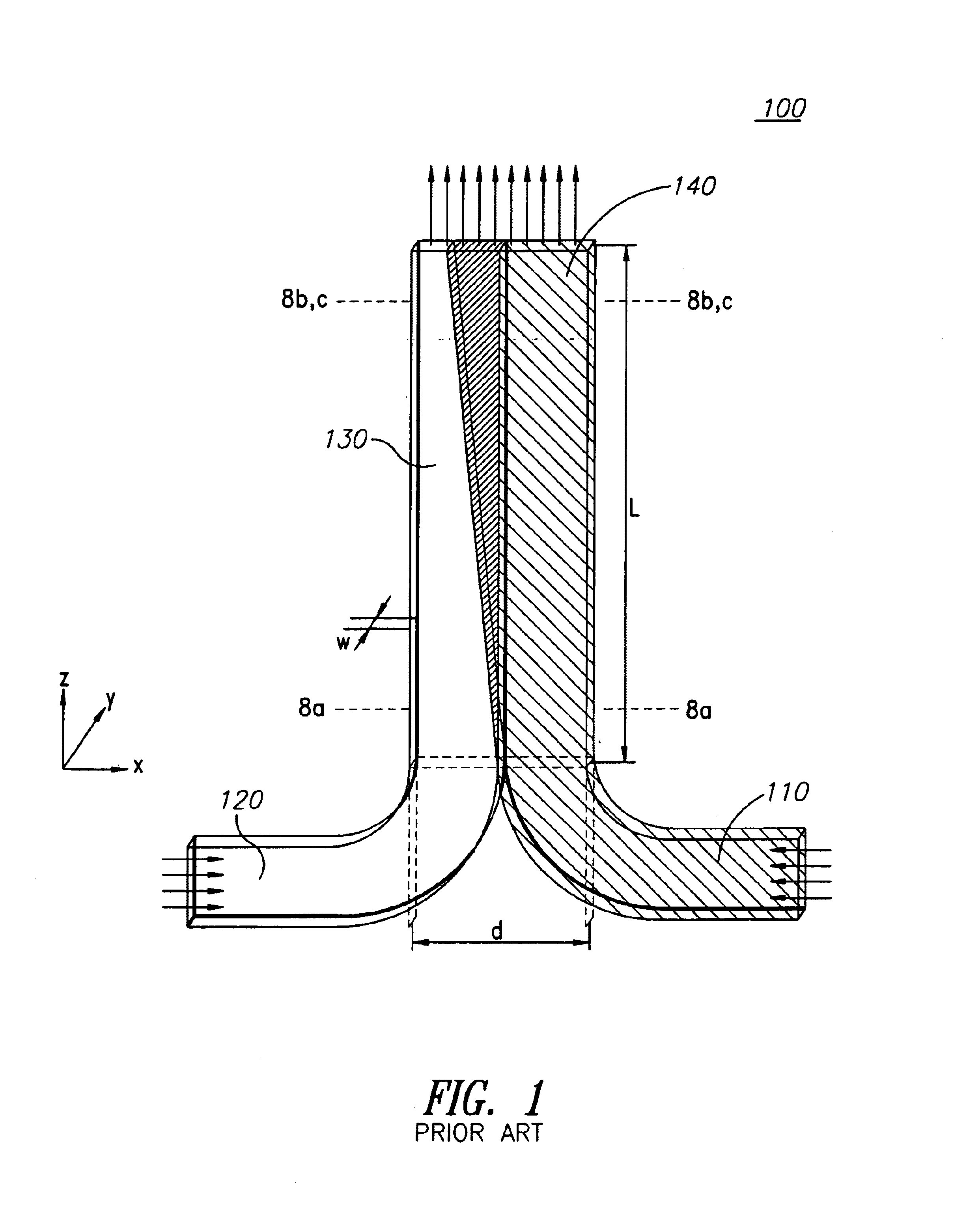
[0094]The diffusion immunoassay (DIA) is a microfluidic assay that allows measurement of the concentration of antigen in a sample. The typical orientation is similar to that of FIG. 1. One fluid contains an antibody for the antigen of interest and the other fluid is the sample spiked with a fluorescent analog of the antigen. The competitive assay relies on interdiffusion of the two fluids and interpretation of the resulting concentration profiles. The DIA has been demonstrated on a small, quickly-diffusing molecule, phenytoin. In some cases, however, it is of interest to apply the DIA scheme to larger slower-diffusing molecules. One such molecule of interest is cardiac troponin I (cTnI), an analyte thought to be a marker of cardiac infarction.

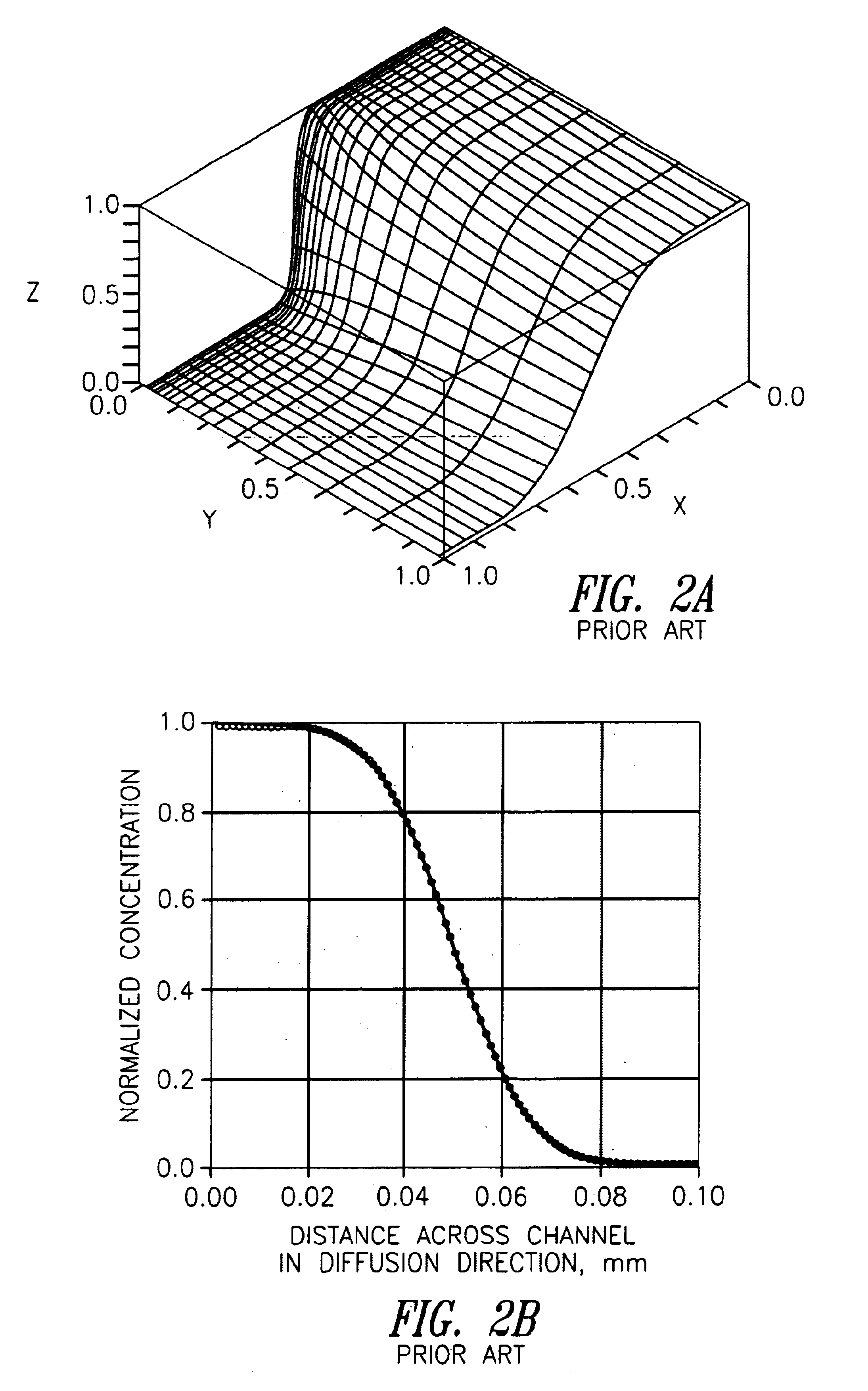
[0095]A one-dimensional model was used to predict fluorescence intensity curves that could...


PUM

PropertyMeasurementUnit
Transparencyaaaaaaaaaa

Abstract

Microfluidic devices and methods are provided for enhancing detection of a diffusion pattern formed by particles diffusing between at least two fluid streams in parallel laminar flow such that an interface is formed between them by increasing the dimension of the streams in the diffusion direction. This may be accomplished by flowing the streams through a transforming turn, or by flowing the streams through a channel having diverging walls. Devices and methods are also provided for enhancing diffusion between two streams comprising changing the interface between said streams from a narrow interface to a broad interface.

Description

CROSS REFERENCE TO RELATED APPLICATIONS[0001]This application claims the benefit of the filing date of U.S. Provisional Application 60 / 233,396 filed Sep. 18, 2000 entitled “Microfluidic Systems and Methods” and U.S. Provisional Application Ser. No. 60 / 269,754 filed Feb. 16, 2001 entitled “Microfluidic Devices for Rotational Manipulation of the Fluidic Interface Between Multiple Flow Streams”, both of which are incorporated herein to the extent not inconsistent herewith.FIELD OF THE INVENTION[0002]This invention relates to microfluidic devices for analysis of liquid samples, and in particular to microfluidic devices having microfluidic channels and turns to convert the aspect ratio from one that is greater than one to one that is less than one.BACKGROUND[0003]Various devices and methods utilizing laminar flow and diffusion principles to detect the presence of and determine the concentration of various analytes in samples, e.g. whole blood, have been described previously. (Weigl, B. H...

Claims


Application Information

Patent Timeline
IPC IPC(8): G01N21/00G01N15/06G01N31/22G01N33/00G01N33/48G01N1/00B01F5/06B01F13/00B01F15/02B01J19/00B01L3/00B81B1/00F15C1/14F15C5/00F16K99/00G01N1/36G01N21/07G01N35/00G01N37/00
CPCB01F5/0646B01F13/0059B01F13/0093B01F15/0203B01F15/0233B01J19/0093B01L3/502776F15C1/14F16K99/0001B01F5/0647Y10T436/117497B01F2005/0031B01F2215/0431B01L2200/0621B01L2200/0636B01L2300/0867B01L2300/087B01L2300/0874B01L2300/161B01L2400/0406B01L2400/0457B01L2400/0655B01L2400/0688F16K2099/0074F16K2099/0078F16K2099/008F16K2099/0084G01N21/07G01N2035/00237G01N2035/00495Y10T436/118339Y10T436/25Y10T436/2575Y10T436/11B01F2025/9171B01F25/4331B01F25/433B01F33/30B01F33/3039B01F35/712B01F35/71725
Inventor WEIGL, BERNHARD H.BARDELL, RONALD L.KAMHOLZ, ANDREWMUNSON, MATTHEWSCHILLING, ERICHAWKINS, KENNETH
Owner UNIV OF WASHINGTON
Why Eureka
Try Eureka