
Intervertebral disk prosthesis

a technology for intervertebral disks and prostheses, which is applied in the field of intervertebral disk prosthesis, can solve the problems of reducing the intrinsic support strength and stability of the disc, affecting the function of the disc, and unable to reverse the damage to the nerve tissu

Inactive Publication Date: 2006-03-14
SPINAL ELEMENTS INC
View PDF44 Cites 163 Cited by
  • Summary
  • Abstract
  • Description
  • Claims
  • Application Information

AI Technical Summary

Benefits of technology

The present invention is an intervertebral disk prosthesis that consists of two parts that can move relative to each other. The first part has a socket that fits into the second part, allowing for at least two degrees of freedom of movement. This design helps to restore the natural movement of the spine and improve the function of the spinal column.

Problems solved by technology

The natural aging process can cause a deterioration of the intervertebral disks, and therefore, their intrinsic support strength and stability is diminished.
Sudden movements may cause a disk to rupture or herniate.
Should the enzyme be injected into the wrong place, or if there is a breach in the disk capsule that would allow the solution to enter the spinal canal or to contact nerve tissue or the like, the resultant damage to nerve tissue could not be reversed.
Even worse, about half of the patients who receive chemonucleolysis treatments experience increased back pain and muscle spasms immediately after the injection and more than half have incapacitating back pain for durations up to three months after such treatments.
This technique is highly invasive and traumatic to the body, and therefore requires an extended recovery time of about five weeks and a hospital stay of a few days.
In addition to the trauma inflicted on the body from even a successful surgery, there are increased risks of future problems due to the removed portion of the lamina 110 which is no longer in place to support and protect the spinal canal 108 at the area where the surgery took place.
Thus, simply removing the disk and parts of the vertebral bone is a short-term, pain-relieving corrective action but not a long-term solution.
While this technique is much less invasive than conventional open surgeries, due to their design the instruments presently available tend to extend the length of time of the surgery and may cause possible damage to areas other than the herniated disk.
The removal of a significant amount of disk material or numerous surgeries often increases the instability of the spine 120 thereby necessitating spinal fusion surgery.
Oftentimes portions of the spine 120 must be immobilized during the recovery period causing added discomfort and inconvenience to the patient.
However, to date, the available nuclear replacements lack the strength of a human disk nucleus pulposus matter and / or the damage to the annulus during implantation may allow extrusion of the nuclear replacement not unlike a disk herniation.
The greatest difficulty to date has been designing a mechanical structure that closely matches that of the human intervertebral disk with regard to such properties as compression, flexion, extension, torsion and the like, not to mention in endurance / durability.
Further, prior art intervertebral disk implants are typically as large as a human intervertebral disk so as to match the vertebrae 100 thereby distributing the compressive loads over a greater area, but necessitating extensive open surgery.
Even worse, critical support materials, such as the ligaments and endplate 110, are usually cut away during the surgical procedure leaving the newly implanted disk replacement with less stability.

Method used


Image

  • Intervertebral disk prosthesis
  • Intervertebral disk prosthesis
  • Intervertebral disk prosthesis

Examples


Embodiment Construction

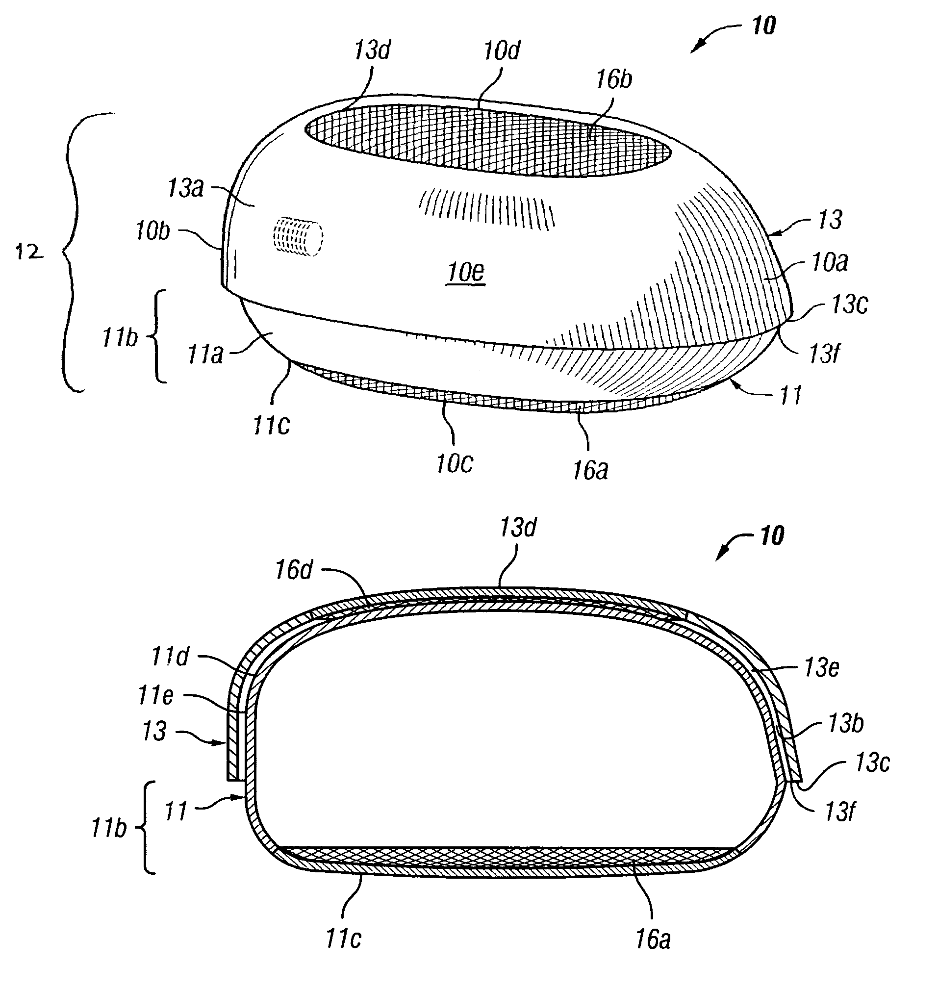
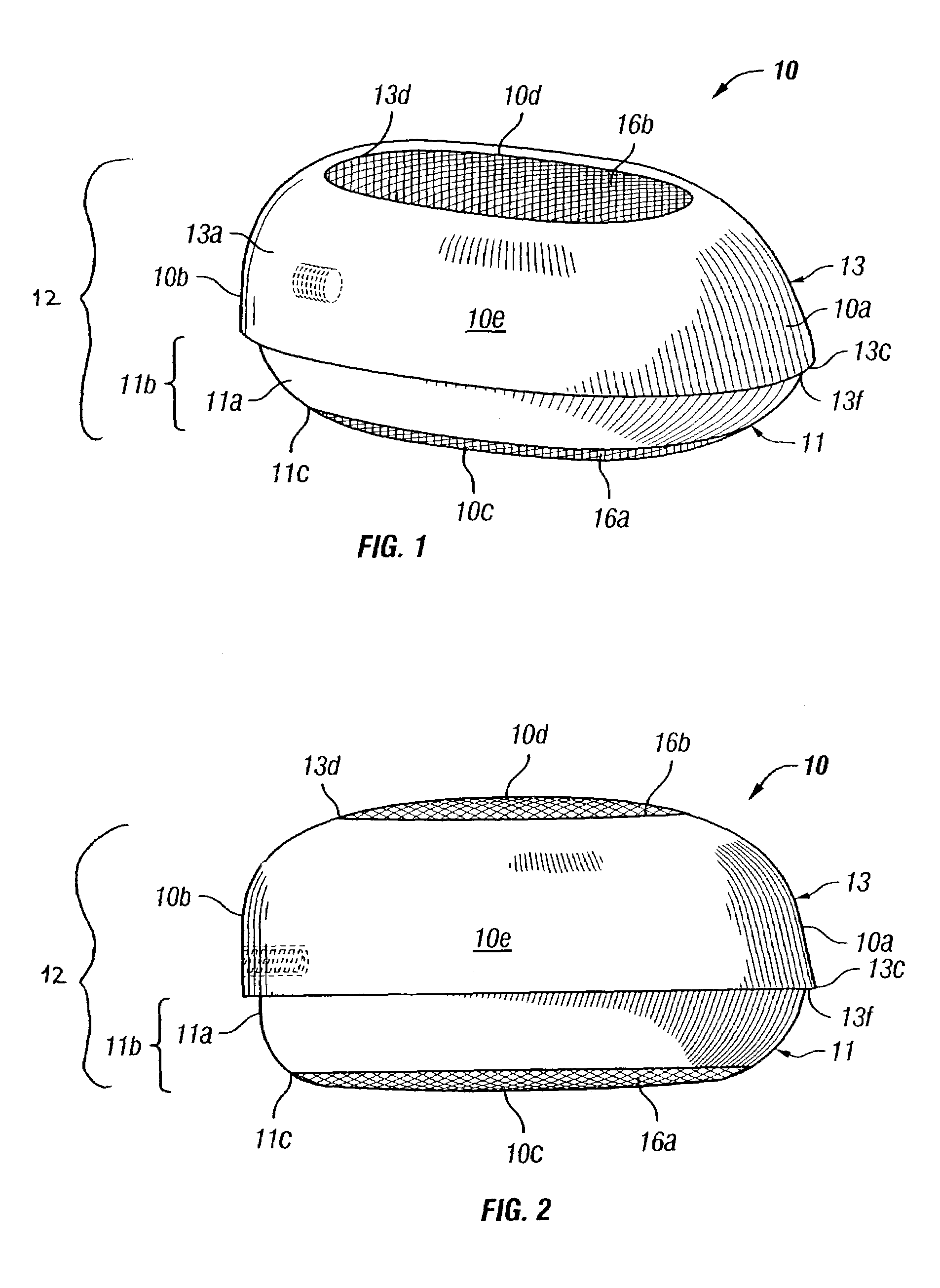
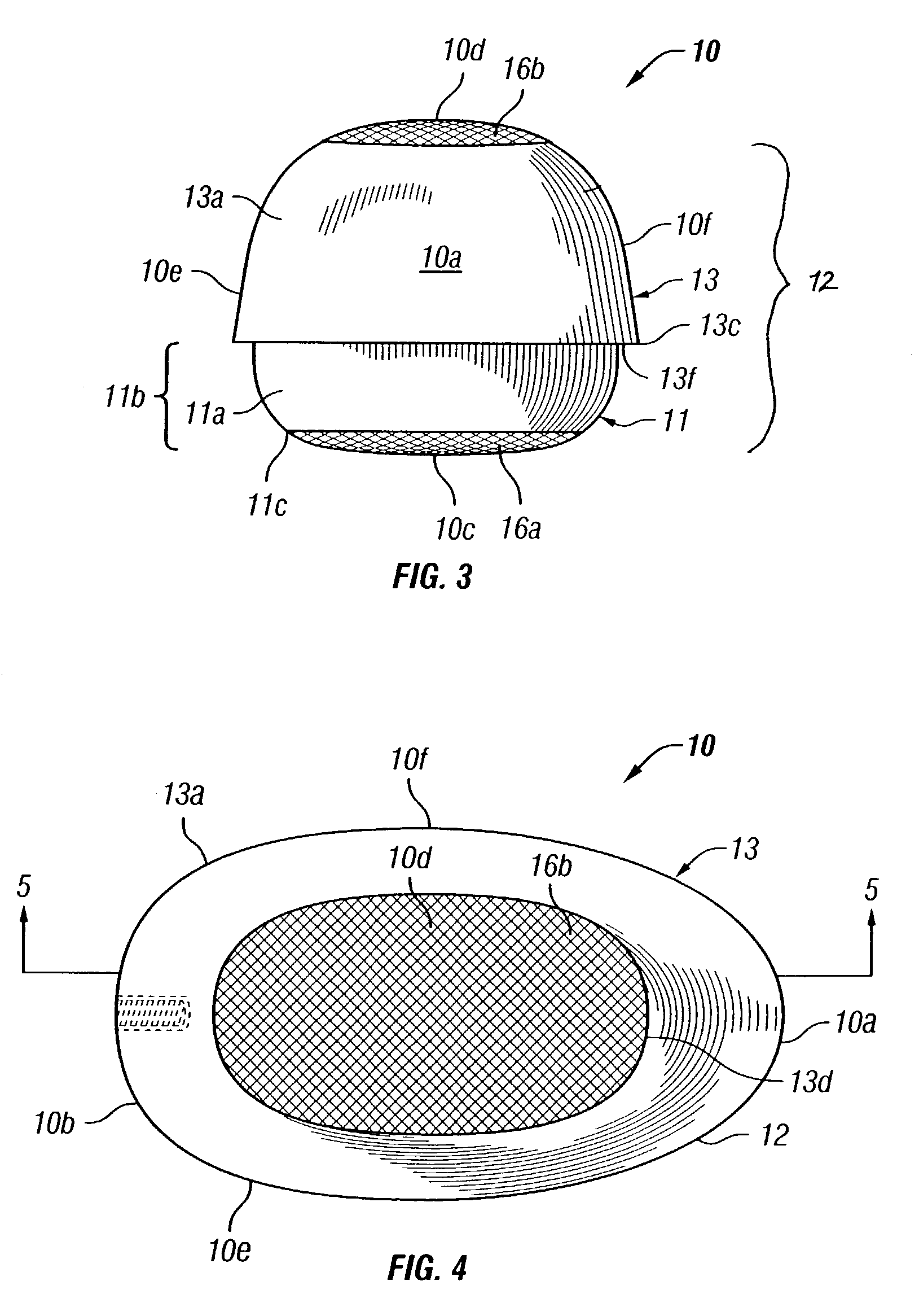
[0043]Certain terminology is used in the following description for convenience only and is not limiting. The words “right”, “left”, “lower”, and “upper” designate directions in the drawing to which reference is made. The words “inwardly” and “outwardly” refer direction toward and away from, respectively, the geometric center of the disk prosthesis and designated parts thereof. The terminology includes the words above specifically mentioned, derivatives thereof and words of similar import. Additionally, the word “a”, as used in the claims and in the corresponding portions of the specification, means “at least one.”

[0044]Referring to the drawings in detail, wherein like reference numerals indicate like elements throughout, there is shown in FIG. 1 an artificial disk or disk prosthesis 10 having a distal end 10a, a proximal end 10b, a lower wall 10c, an upper wall 10d, a first sidewall 10e and a second sidewall 10f (FIGS. 3, 4). The disk prosthesis 10 includes a first part or a cap 13....


PUM

PropertyMeasurementUnit
lengthaaaaaaaaaa
lengthaaaaaaaaaa
widthaaaaaaaaaa

Abstract

An intervertebral disk prosthesis includes a first part, and the first part has a top, a bottom having an opening, an outer surface, an inner surface and a socket extending into an interior of the first part from the opening and defined by the inner surface. The outer surface proximate the top contacts a concave portion of a first vertebra. The disk prosthesis further includes a second part including a top, a bottom, and an outer surface. The outer surface proximate the bottom contacts a concave portion of a second vertebra, and the outer surface of the second part proximate the top of the second part cooperatively engages the inner surface of the first part thereby allowing at least two-degrees of freedom of movement.

Description

CROSS-REFERENCES TO RELATED APPLICATIONS[0001]This application claims the benefit of U.S. Provisional Application No. 60 / 369,667 filed Apr. 2, 2002 entitled “DISK PROSTHESIS” and U.S. Provisional Application No. 60 / 349,743 filed Jan. 17, 2002 entitled “DISK PROSTHESIS,” the entire contents of which are incorporated by reference herein.BACKGROUND OF THE INVENTION[0002]The present invention relates to an apparatus for intervertebral disk replacement and more particularly to an intervertebral disk prosthesis capable of being implanted in a patient utilizing minimally invasive surgical techniques.[0003]Referring to prior art FIGS. 9 and 10, the spine 120, also known as the vertebral column or the spinal column, is a flexible column of vertebrae 100 (special types of bones) held together by muscles, ligaments and tendons. The spine 120 extends from the cranium (not shown) to the coccyx 126, encasing a spinal cord 128 and forming the supporting axis of the body (not shown). The spinal cor...

Claims


Application Information

Patent Timeline
Patent Type & Authority Patents(United States)
IPC IPC(8): A61F2/44A61B17/58A61F2/00A61F2/30A61F2/46
CPCA61F2/4611A61F2/4425A61F2/30907A61F2310/00796A61F2002/30112A61F2002/30242A61F2002/30253A61F2002/30331A61F2002/30462A61F2002/3049A61F2002/30649A61F2002/30685A61F2002/30784A61F2002/30797A61F2002/30807A61F2002/4623A61F2002/4627A61F2002/4629A61F2220/0025A61F2220/0033A61F2220/0075A61F2230/0004A61F2230/0071A61F2230/0076A61F2310/00017A61F2310/00023A61F2310/00029A61F2310/00179A61F2/4603
Inventor ECKMAN, WALTER W.
Owner SPINAL ELEMENTS INC
Learn More