
Thermal type flow measuring instrument with mold casing in metal insert

a technology of air flow and measuring instrument, which is applied in the direction of instruments, machines/engines, electric control, etc., can solve the problems of cracks and cracks in the interior and the surface of the resin portion, and achieve the effects of preventing the lowering of the resonant frequency, high rigidity, and large mass

Inactive Publication Date: 2006-03-14
HITACHI ASTEMO LTD
View PDF11 Cites 24 Cited by
  • Summary
  • Abstract
  • Description
  • Claims
  • Application Information

AI Technical Summary

Benefits of technology

This approach effectively suppresses the occurrence of cracks and retards fatigue crack growth, enhancing the reliability of the air flow measuring instrument by optimizing resin strength and fiber orientation, thereby improving the instrument's durability and performance.

Problems solved by technology

However, the above conceivable solution would raise the following problems.
Because the housing fixing portion has a structure made up of two kinds of materials, i.e., a metal plate portion and a resin portion, stresses are caused upon a deformation due to a difference in thermal expansion coefficient between resin and metal, whereby cracks are produced in the resin portion of the housing fixing portion.
Also, the cracks may produce in both the surface and the interior of the resin portion.

Method used


Image

  • Thermal type flow measuring instrument with mold casing in metal insert
  • Thermal type flow measuring instrument with mold casing in metal insert
  • Thermal type flow measuring instrument with mold casing in metal insert

Examples


first embodiment

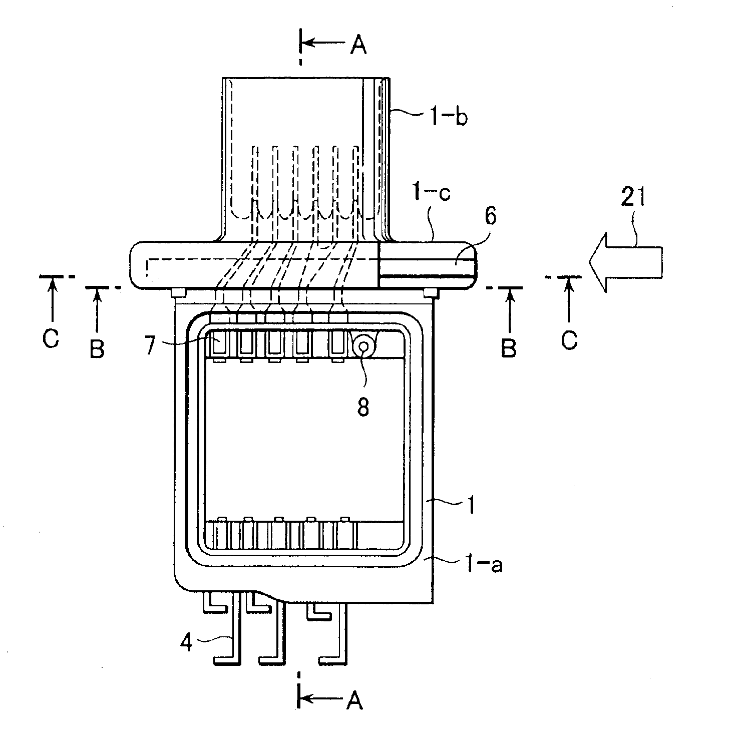
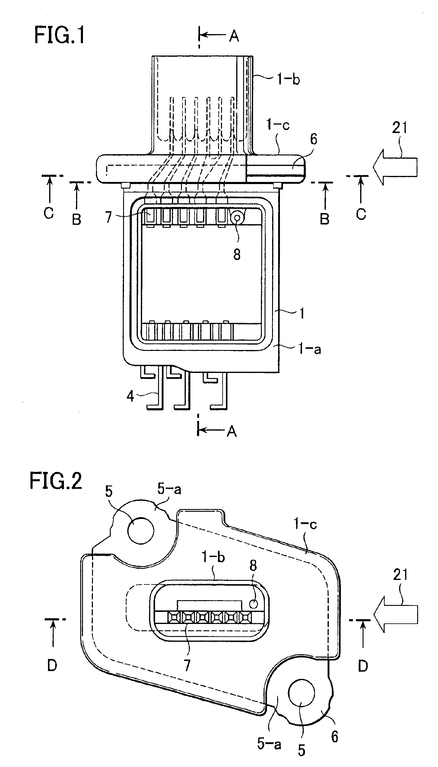
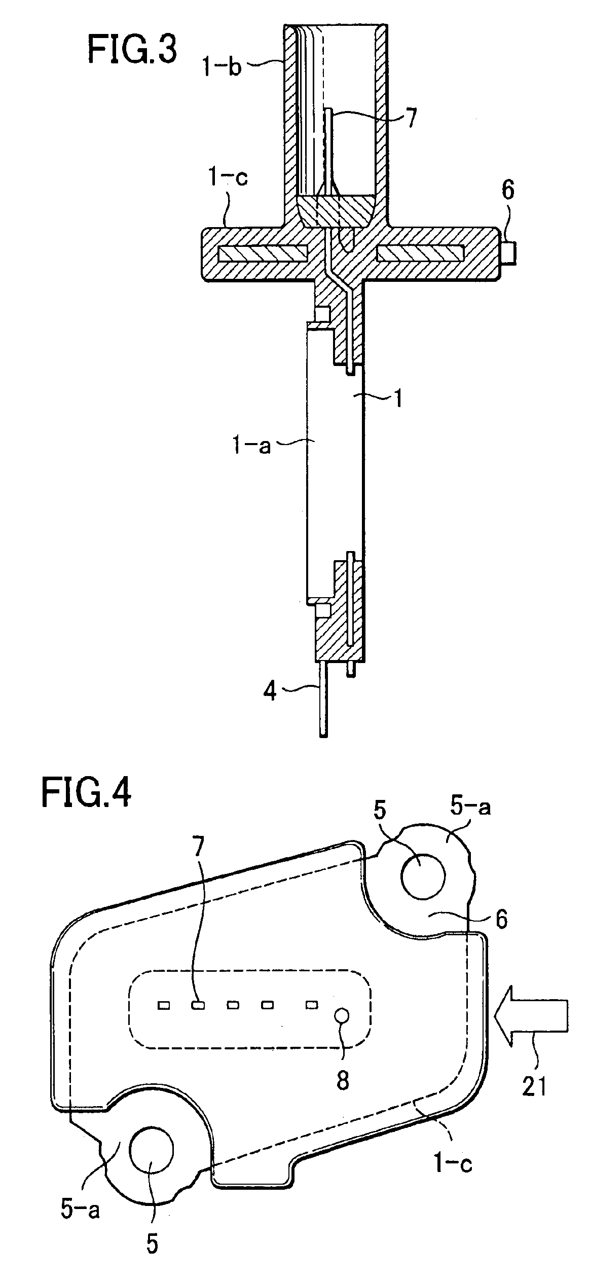
[0072]FIG. 1 is a front view of a molded part for use in a thermal type air flow measuring instrument according to the present invention, the molded part being formed by integral molding with a metal plate inserted therein, and FIG. 2 is a plan view of the molded part shown in FIG. 1. FIG. 3 is a sectional view of the molded part taken along line A—A in FIG. 1, FIG. 4 is a sectional view of the molded part taken along line B—B in FIG. 1, FIG. 5 is a sectional view of the molded part taken along line C—C in FIG. 1, and FIG. 6 is a sectional view of the molded part taken along line D—D in FIG. 2. FIG. 7 shows a flow duct, as viewed from the upstream side, in one embodiment of the thermal type air flow measuring instrument using the molded part shown in FIG. 1. FIG. 8 is a plan view of the thermal type air flow measuring instrument shown in FIG. 7, and FIG. 9 is a sectional view of the thermal type air flow measuring instrument taken along line E—E in FIG. 8.

[0073]A housing 1 comprises...

second embodiment

[0133]FIG. 29 is a sectional view of a throttle body 34 having a valve 33 to control intake air in an engine, the view showing the present invention. In the throttle body 34, an air flow meter integrally provided with an auxiliary passage is arranged upstream of the valve 33. The air flow meter has the same structure as that of one of the examples shown in FIGS. 1 to 27, and can provide similar working advantages to those ones obtained with them.

[0134]While the second embodiment has been described in connection with the throttle body 34, the present invention is also applicable to other type of body having the valve 33 to control intake air in an engine, e.g., an ETC (Electric Throttle) body, while ensuring the similar working advantages.

[0135]FIG. 30 is a partial sectional view of an air cleaner 35 disposed in an engine room, the view showing a second embodiment of the present invention. The air cleaner 35 has a structure in which a filter member 36 for removing dust is fixedly san...


PUM

PropertyMeasurementUnit
temperature stressaaaaaaaaaa
thermal type flow measuring instrumentaaaaaaaaaa
speedsaaaaaaaaaa

Abstract

The invention is intended to improve reliability of a thermal type air flow measuring instrument employing a molded part formed by integral molding together with a metal plate. A slot or opening allowing only a resin to pass through the same is formed in the metal plate in an area or thereabout subjected to higher stresses. A part of connector terminals, which is not required from the intrinsic object, is disposed in the vicinity of a area where the resin has a larger thickness and the temperature difference between the inside and the outside of the resin is locally increased. An injecting direction is set so as to prevent a weld line and a void from being generated in a combined way. In the molded part with the metal plate inserted therein, the occurrence of cracks and an increase of the fatigue crack growth rate can be suppressed and reliability can be improved.

Description

BACKGROUND OF THE INVENTION[0001]1. Field of the Invention[0002]The present invention relates to a thermal type air flow measuring instrument for measuring an air flow taken into an internal combustion engine of an automobile, the instrument including a plastic part that is formed by integral molding with a metal part inserted therein.[0003]2. Description of the Related Art[0004]Japanese Publication of unexamined patent application No. 11-14423 discloses one example of the related art regarding a thermal type air flow measuring instrument using a molded part. In the disclosed instrument, a housing formed as a molded part comprises a frame shaped portion incorporating an electronic circuit therein and protecting it, a connector portion for electrical connection between an external device and the electronic circuit, and a fixing portion for fixing the thermal type air flow measuring instrument in place. Thus, the known thermal type air flow measuring instrument has a structure in whic...

Claims


Application Information

Patent Timeline
Patent Type & Authority Patents(United States)
IPC IPC(8): G01F1/68G01M99/00B29C45/00F02D35/00F02D41/18G01F1/684
CPCG01F1/6842B29C45/0025
Inventor KOZAWA, MASAYUKIIGARASHI, SHINYAHIRAMATSU, NOBUHITOSAITO, NAOKIKIKAWA, HIROMU
Owner HITACHI ASTEMO LTD
Learn More