
High-frequency two-dimensional antenna and associated down-conversion method

a two-dimensional antenna and high-frequency technology, applied in the field of optical antennas, micrometer and sub-millimeter wave and individual energised antenna arrays, resonant antennas, antenna supports/mountings, etc., can solve problems such as interference with the operation of electronics

Active Publication Date: 2006-03-07
THE BOEING CO
View PDF8 Cites 35 Cited by
  • Summary
  • Abstract
  • Description
  • Claims
  • Application Information

AI Technical Summary

Benefits of technology

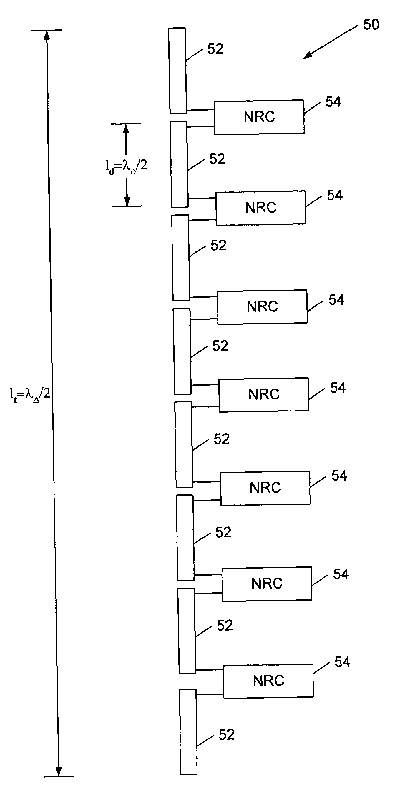
The invention is a high-frequency two-dimensional antenna that can receive signals with two different frequencies and convert them to a third frequency using a nonlinear resonant circuit. The antenna can be rotated to steer the direction of signal re-radiation. The distance between adjacent antennas can be adjusted to control the direction of signal re-radiation. The antenna includes a plurality of dipole antennas and nonlinear circuit elements that allow for the down-conversion of the two frequencies to the difference frequency. The method of down-converting the two frequencies involves transmitting them in intersecting directions or combining them through a polarization beam combiner. The technical effects of the invention include improved signal reception and reduced interference.

Problems solved by technology

When the interference difference frequency is incident upon electronic components at or near the interference frequency, the resultant field will interfere with the operation of the electronics.

Method used


Image

  • High-frequency two-dimensional antenna and associated down-conversion method
  • High-frequency two-dimensional antenna and associated down-conversion method
  • High-frequency two-dimensional antenna and associated down-conversion method

Examples


Embodiment Construction

[0022]The present invention now will be described more fully hereinafter with reference to the accompanying drawings, in which preferred embodiments of the invention are shown. This invention may, however, be embodied in many different forms and should not be construed as limited to the embodiments set forth herein; rather, these embodiments are provided so that this disclosure will be thorough and complete, and will fully convey the scope of the invention to those skilled in the art. Like numbers refer to like elements throughout.

[0023]Electromagnetic radiation in the RF (radio frequency), microwave, millimeter and optical wave ranges interacts with thin conducting bodies, such as wires when the conductor is aligned with the electric field of radiation. The interaction is dependent upon conductor length, l, in relation to the radiation wavelength, λ. A half wavelength dipole antenna, for example, will resonate and reradiate for a conductor length that is one half the radiation wave...


PUM


Abstract

A high-frequency two-dimensional antenna includes a plurality of dual-frequency antennas configured to receive signals having first and second frequencies above the microwave band of the electromagnetic spectrum. The dual-frequency antennas of the two-dimensional antenna are arrayed to an effective length to re-radiate signals at a third frequency, which is down-converted from the first and second frequencies. Each dual-frequency antenna of the two-dimensional antenna includes a plurality of dipole antennas, and a plurality of nonlinear resonant circuits. The nonlinear resonant circuits interconnect the dipole antennas and are configured to permit re-radiation of signals having the third frequency over the effective length. A method of down-converting signals having at least first and second electromagnetic radiation frequencies is also provided.

Description

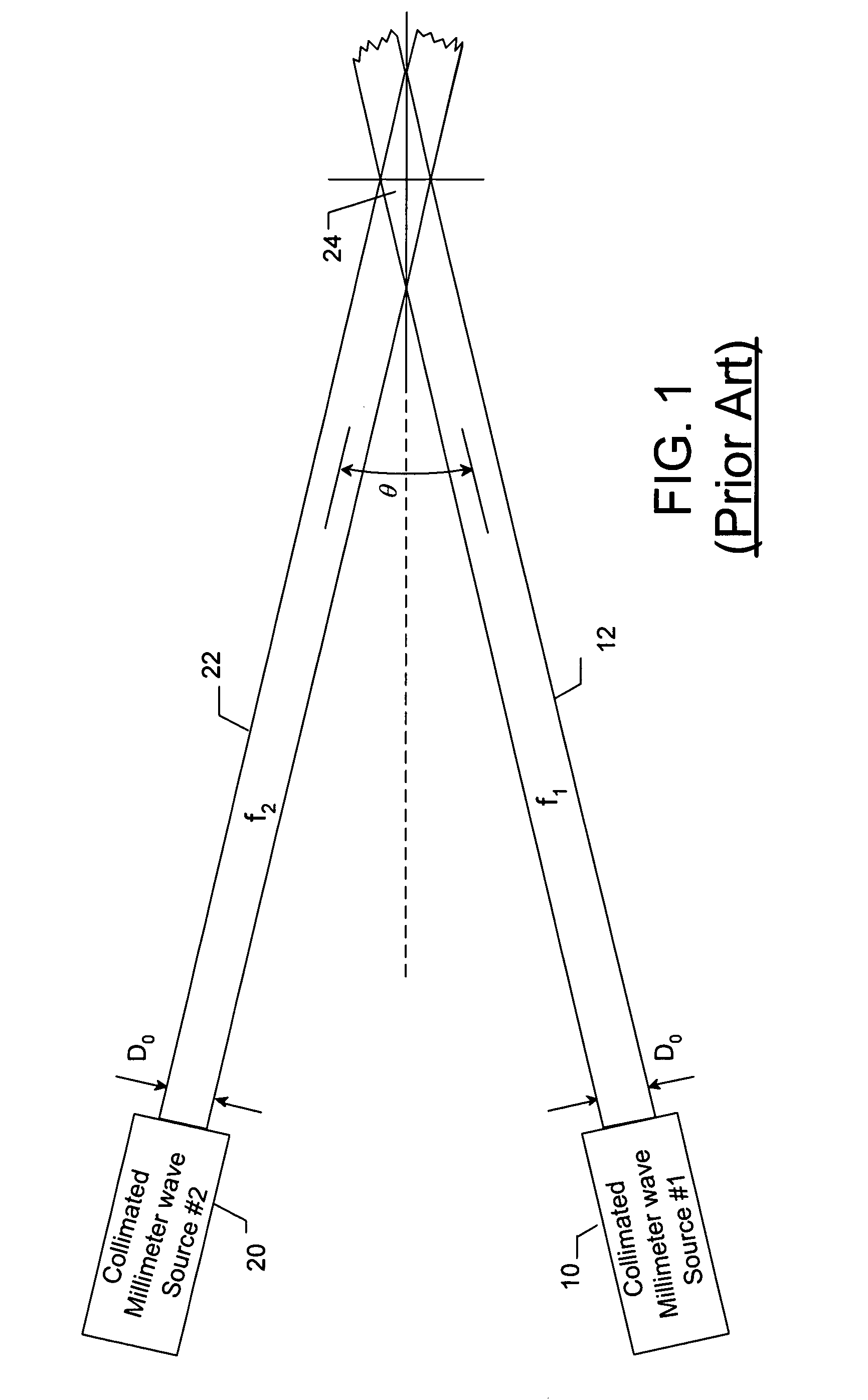
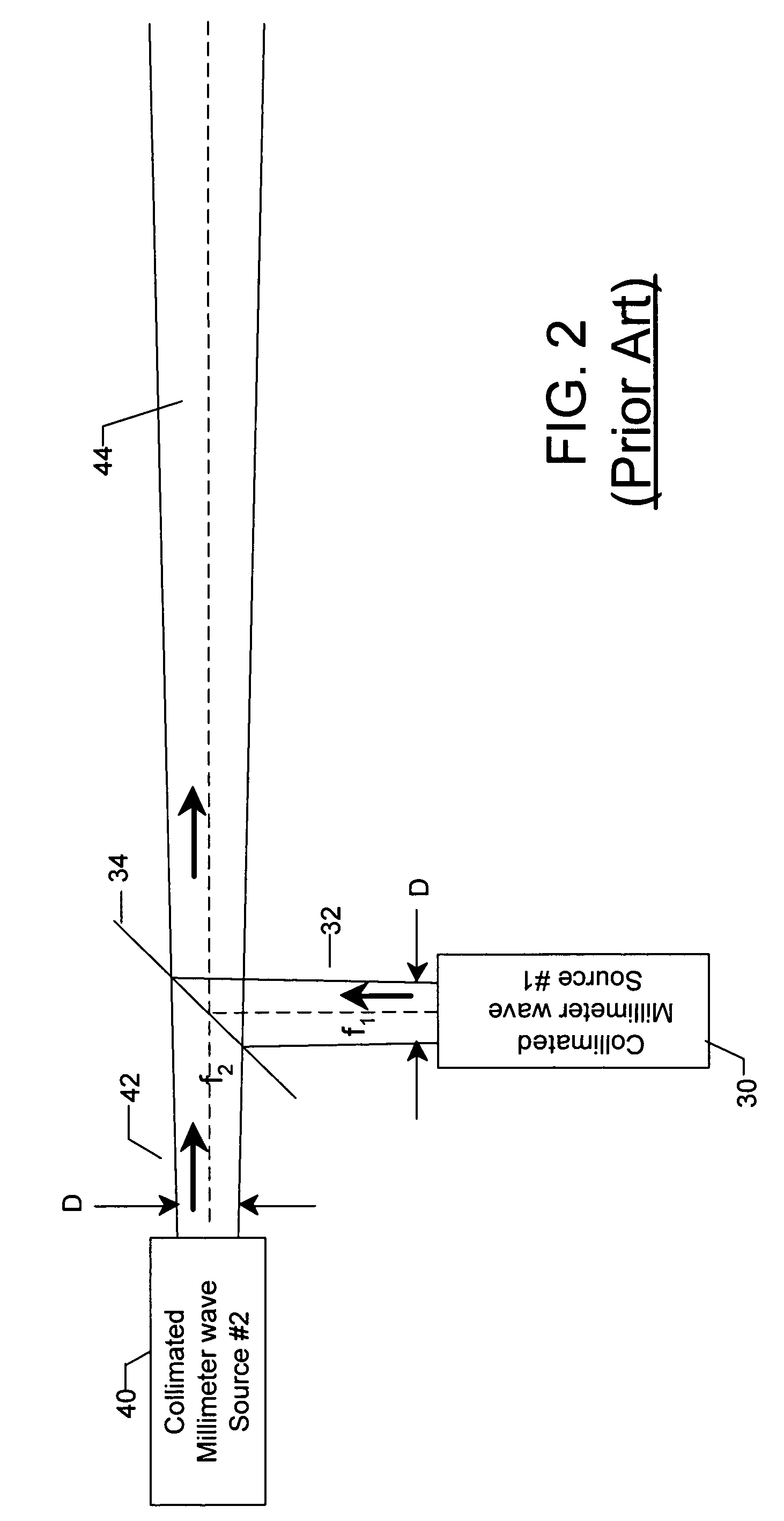
FIELD OF THE INVENTION[0001]The present invention relates to a millimeter and submillimeter wave and optical antennas, and more particularly, to a high-frequency two-dimensional antenna and associated method for converting electromagnetic radiation from a first and second frequency to a third, a difference frequency and reradiating the resulting difference frequency.BACKGROUND OF THE INVENTION[0002]As described in co-pending U.S. patent application Ser. No. 10 / 444,510 incorporated herein by reference, FIG. 1 illustrates two sources of electromagnetic radiation collimated millimeter wave sources 10, 20 radiating collimated beams 12, 22 of electromagnetic radiation at two separate frequencies, f1 and f2, and in two intersecting directions that produce interference at a distance. Generally, when two electromagnetic beams of different frequencies converge, the volume of the intersection 24 will include a frequency component which is equal to the difference in frequency of the two beams,...

Claims


Application Information

Patent Timeline
Patent Type & Authority Patents(United States)
IPC IPC(8): H01Q9/16H01Q1/24H01Q5/00H01Q23/00
CPCH01Q23/00H01Q1/247
Inventor HOLLY, SANDORKOUMVAKALIS, NICHOLAS
Owner THE BOEING CO
Learn More