Ink-jet head and ink-jet printer having ink-jet head
a technology of inkjet printer and inkjet head, which is applied in the direction of printing and inking apparatus, etc., can solve the problems of crosstalk and the deterioration of the image quality of the image recording medium, and achieve the effect of preventing crosstalk
- Summary
- Abstract
- Description
- Claims
- Application Information
AI Technical Summary
Benefits of technology
Problems solved by technology
Method used
Image

Examples
first embodiment
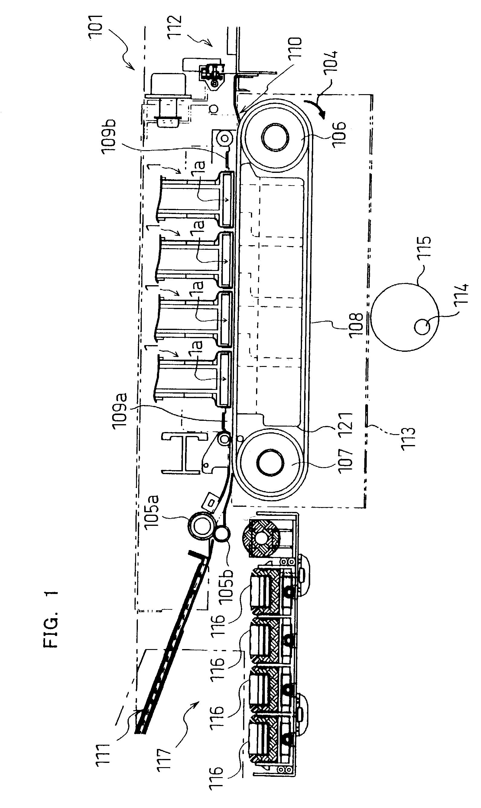
[0029]FIG. 1 is a schematic view of an ink-jet printer having ink-jet heads according to the invention. As shown in FIG. 1, the ink-jet printer 101 is a color ink-jet printer having four ink-jet heads 1. In this exemplary embodiment, the printer 101 has an image recording medium feed unit 111 and an image recording medium discharge unit 112, which are disposed on the left and right portions printer 101 of FIG. 1, respectively. In various exemplary embodiments, the image recording medium includes, for example; a sheet of paper, card stock, photo paper, a transparency, or the like.
[0030]The ink-jet printer 101 includes an image recording medium transfer path that extends from the image recording medium feed unit 111 to the image recording medium discharge unit 112. A pair of feed rollers 105a and 105b is disposed immediately downstream of the image recording medium feed unit 111 for pinching and putting forward an image recording medium. By the pair of feed rollers 105a and 105b, the ...
second embodiment
[0107]FIG. 13 is an enlarged plan view of an actuator unit in an ink-jet head according to the present invention. FIG. 14 is a sectional view taken along line XIII—XIII in FIG. 13.
[0108]Referring to FIG. 13, in the ink-jet head of this embodiment, between two individual electrodes 35 neighboring each other in the first arrangement direction on the upper face of an actuator unit 21′, a substantially straight groove 61c is provided in parallel with the longer diagonal of each main electrode portion 35a to correspond to the portion other than the vicinity of the acute portion of each main electrode portion 35a. Referring to FIG. 14, each groove 61c is formed through the actuator unit 21′ and has its bottom on the upper face of the cavity plate 22.
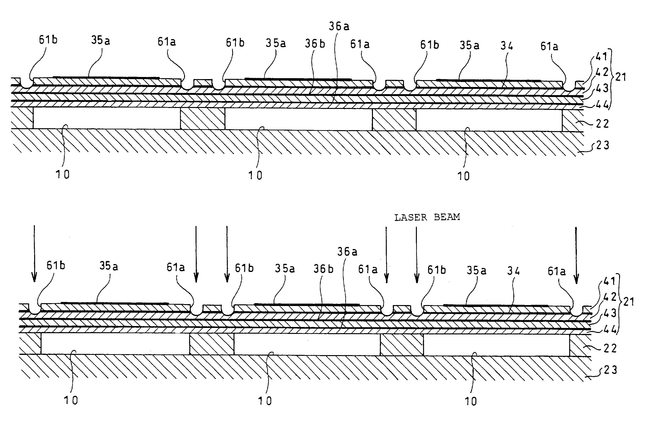
[0109]The thus constructed actuator unit 21′ is manufactured as follows. That is, as described above, a conductive paste to be a reinforcement metallic film 36b or a common electrode 34 is printed in a pattern on each piezoelectric sheet to co...
third embodiment
[0114]Next, an ink-jet head according to the present invention will be described. FIG. 15 is an enlarged plan view of an actuator unit in an ink-jet head according to this embodiment.
[0115]Referring to FIG. 15, in the ink-jet head of this embodiment, a substantially straight groove 61d is provided in the upper face of an actuator unit to extend from a position somewhat distant from the lower right side of the main electrode portion 35a of each individual electrode 35 and substantially the same as the inner wall of the corresponding pressure chamber 10 in a plan view (except the vicinity of the acute portion of the main electrode portion 35a), to a portion somewhat distant from the upper left side of the main electrode portion 35a of the individual electrode 35 neighboring the right side of the above individual electrode 35 in the first arrangement direction and at substantially the same position as the inner wall of the corresponding pressure chamber 10 in a plan view (except the vi...
PUM
 Abstract
Description
Claims
Application Information
 - R&D
- Intellectual Property
- Life Sciences
- Materials
- Tech Scout
- Unparalleled Data Quality
- Higher Quality Content
- 60% Fewer Hallucinations
Browse by: Latest US Patents, China's latest patents, Technical Efficacy Thesaurus, Application Domain, Technology Topic, Popular Technical Reports.
© 2025 PatSnap. All rights reserved.Legal|Privacy policy|Modern Slavery Act Transparency Statement|Sitemap|About US| Contact US: help@patsnap.com