
Media storage bin and method of using same

a media storage bin and bin bin technology, applied in the field of printing devices, can solve the problems of large size, high cost, and environment that is detrimental to the printhead, and achieve the effect of constant fall distan

Inactive Publication Date: 2006-03-07
HEWLETT PACKARD DEV CO LP
View PDF17 Cites 2 Cited by
  • Summary
  • Abstract
  • Description
  • Claims
  • Application Information

AI Technical Summary

Benefits of technology

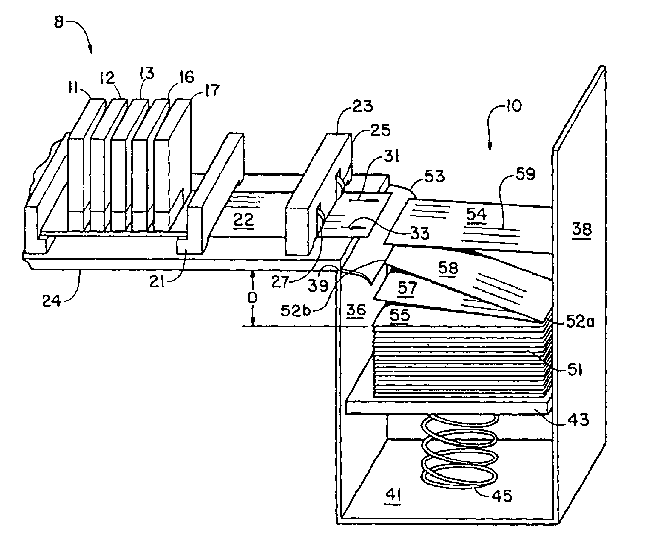
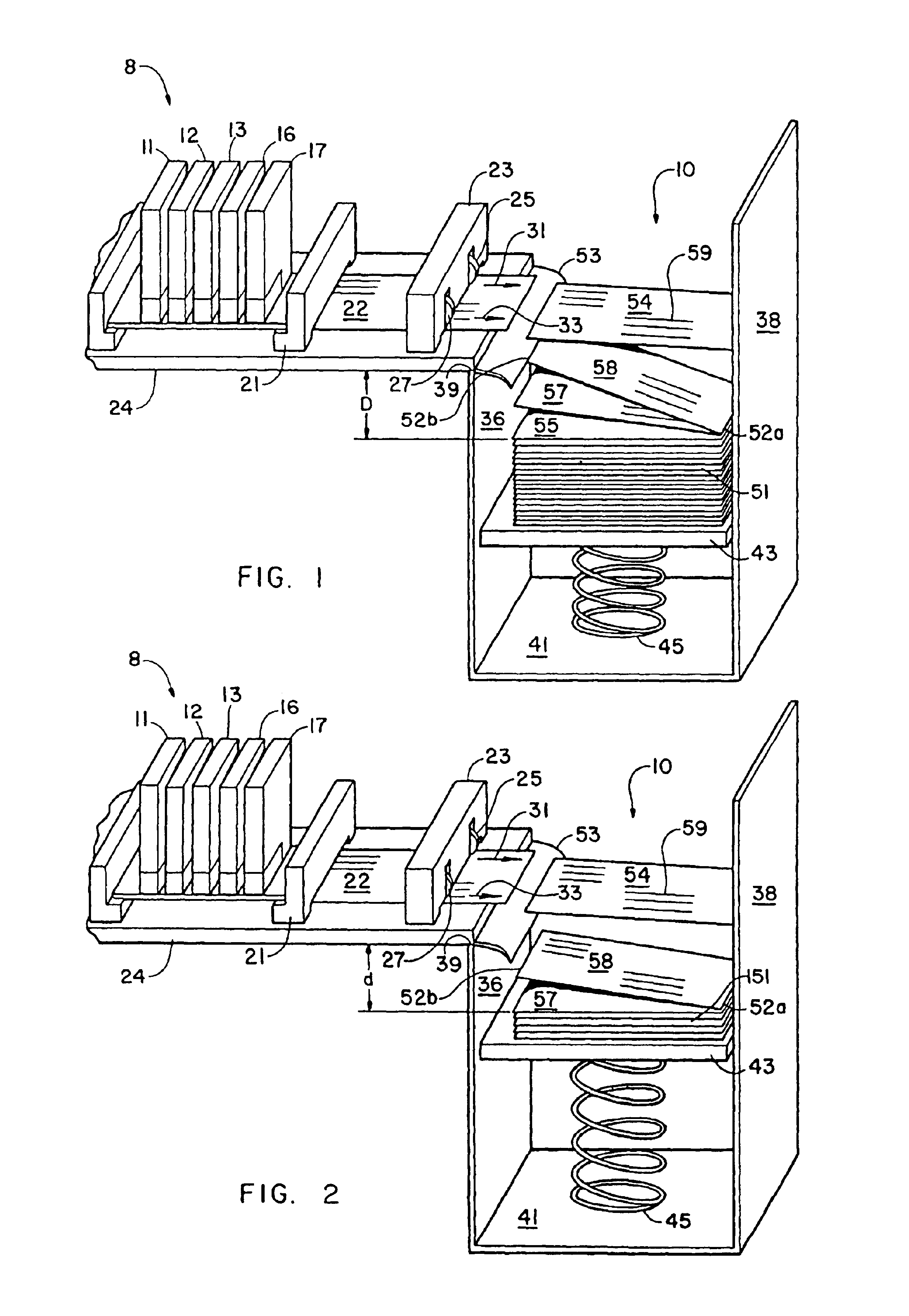
[0007]According to the present invention, there is provided a media storage bin including a floor and a pair of spaced apart walls specifically spaced to receive pieces of media and to retain the pieces of media in a stacked condition. A drop control flap is mounted to an individual one of the spaced walls for delaying the fall of a piece of media into the bin. This wall includes a top surface. A platform for supporting a stack of pieces of media is disposed in the bin, between the wall top surface and the floor. A helical spring is disposed between the platform and the floor for maintaining the top of the media stack at a predetermined distance from the wall top surface to provide thereby a constant fall distance between an individual one of the pieces of media and the wall top surface. This is accomplished in a manner whereby the spring rate enables the platform to drop the thickness of one piece of media for each piece of media added to the top of the stack.
[0008]The media storage bin of the present invention affords several advantages. It enables increased throughput without any sacrifice of print quality. It is inexpensive to produce since the control flap is constructed of readily available materials and the helical spring can be procured without difficulty. Importantly, the invention eliminates the need for heaters while providing a simple and reliable technique for stacking pieces of printed media while substantially eliminating rubbing of the pieces during the stacking process. As a result, the smearing problem is substantially eliminated in an efficient and effective manner.

Problems solved by technology

Such heaters are relatively large and expensive.
In addition, the heaters can present a potential fire hazard and, since they dry the air around the printheads, they create an environment that is detrimental to the printheads.
Thus, use of heaters to eliminate smearing may have some utility but the technique itself presents some limitations.

Method used


Image

  • Media storage bin and method of using same
  • Media storage bin and method of using same

Examples


Embodiment Construction

[0012]The present invention may be embodied in other specific forms without departing from its spirit or essential characteristics. The described embodiment is to be considered in all respects only as illustrative and not restrictive. The scope of the invention is, therefore, indicated by the appended claims rather than by the foregoing description. All changes that come within the meaning and range of equivalency of the claims are to be embraced within their scope.

[0013]In the following detailed description and in the drawings, like elements are identified with like reference numerals. As shown in the drawings for purposes of illustration, the invention is embodied in a novel media storage bin for receiving and stacking printed pieces of media. A drop control flap aids in preventing rubbing one media piece against another, thereby substantially reducing smearing while the spring maintains a constant fall distance for the media pieces.

[0014]Referring now to FIG. 1 of the drawings, t...


PUM


Abstract

A media storage bin including a floor and a pair of spaced apart walls specifically spaced to receive pieces of media and to retain the pieces of media in a stacked condition. A drop control flap is mounted to an individual one of the spaced walls for delaying the fall of a piece of media into the bin. This wall includes a top surface. A platform for supporting a stack of pieces of media is disposed in the bin, between the wall top surface and the floor. A helical spring is disposed between the platform and the floor for maintaining the top of the media stack at a predetermined distance from the wall top surface to provide thereby a constant fall distance between an individual one of the pieces of media and the wall top surface. This is accomplished in a manner whereby the spring rate enables the platform to drop the thickness of one piece of media for each piece of media added to the top of the stack.

Description

[0001]This application is a continuation of and claims the priority of an application entitled MEDIA STORAGE BIN AND METHOD OF USING SAME, application Ser. No. 09 / 539,055 filed Mar. 30, 2000 now U.S. Pat. No. 6,631,902.BACKGROUND OF THE INVENTION[0002]The present invention relates generally to printing devices and, more particularly, to a printer media storage bin and method of using the same.[0003]Modern printing devices utilize printheads or drop ejectors that are often mounted in a carriage that is moved back and forth across print media, such as paper or envelopes, for example. During the printing process, as the printheads move across the print media, a control system activates the printheads to deposit or eject ink droplets onto the print media to form images and text.[0004]Throughput is often an important factor in printing processes and, as a result, a printer manufacturer can be under pressure to find techniques for increasing throughput, without diminishing print quality. ...

Claims


Application Information

Patent Timeline
Patent Type & Authority Patents(United States)
IPC IPC(8): B65H31/14B65H29/52B65H31/10
CPCB65H29/52B65H31/14B65H31/10
Inventor BEAUCHAMP, ROBERT WARREN
Owner HEWLETT PACKARD DEV CO LP
Learn More