
Water-diverting windshield wiper blades

a wiper blade and windshield wiper technology, applied in the field of reciprocating wipers, can solve the problems of reducing visibility, driver or pilot side, and consequently significant visibility reduction, and achieve the effect of increasing the efficiency of liquid removal by the wiper

Inactive Publication Date: 2006-03-07
JAMES ALBERT J
View PDF24 Cites 13 Cited by
  • Summary
  • Abstract
  • Description
  • Claims
  • Application Information

AI Technical Summary

Benefits of technology

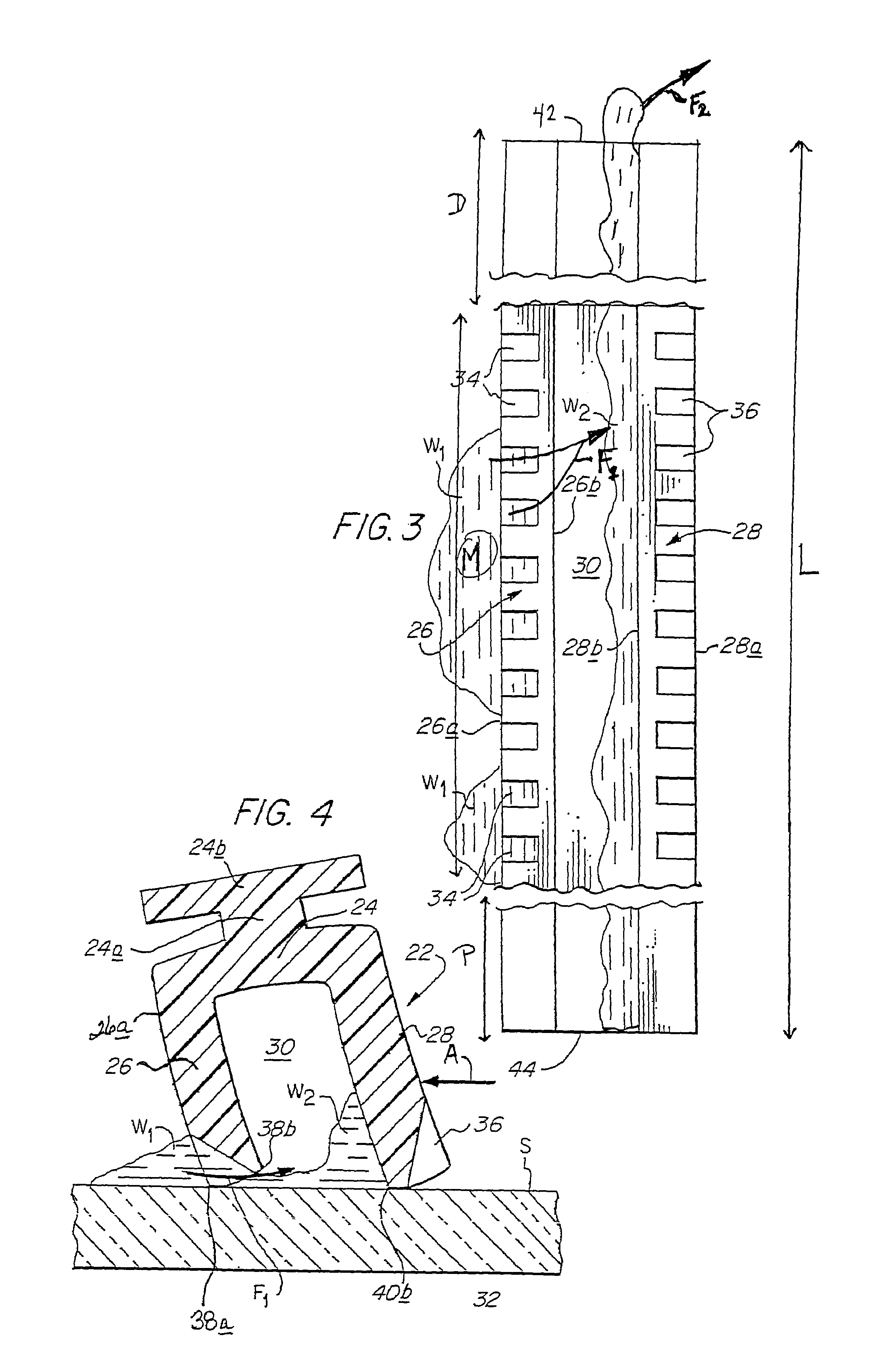
[0015]Generally, the present invention provides a wiper, e.g., a windshield wiper, comprising two or more blades, e.g., a first blade and a second blade, disposed relative to each other so that, at least when the wiper is in use, the blades define therebetween a longitudinal channel which is open at its distal end and, preferably, is also open at its proximal end. Each blade is considered to comprise a middle segment disposed between a proximal segment and a distal segment, and at least one, but preferably both, of the blades have one or more formations, such as notches, slits or protrusions, disposed along a middle segment of the blade or blades and excluded from at least the distal segment of the blade or blades. The formations are configured so that as the blade is moved in reciprocating fashion across a surface, e.g., across the surface of a windshield, water (or other liquid) on the surface passes through the formations and under the blade when the wiper is moving in one direction, so that the water or other liquid may flow through the longitudinal channel and be discharged at one or both ends of the wiper, but does not pass through the formations, and is thereby wiped by the blade, when the wiper is moving in the opposite direction. The discharge of the water or other liquid is believed to be facilitated by a combination of Venturi and centrifugal force effects because the distal end of the wiper is moving faster than the proximal end through the typical arc-shaped travel path of the wiper. At least the distal and, preferably, both the proximal and distal, segments of the blade or blades are left free of formations which would permit water or other liquid to flow through the blade, because it has been found that the efficiency of liquid removal by the wiper is increased by doing so.

Problems solved by technology

One difficulty with this arrangement is that each reciprocating wiper assembly at the “inside” end of its travel path pushes some or all of the water it has cleared into the cleared arc of the adjacent wiper assembly.
The accumulated water pushed into the cleared arc of the adjacent assembly reduces visibility through a windshield or the like and, especially on the driver's or pilot's side, presents a hazard.
The consequent reduction in visibility can be significant, especially in very heavy downpours of rain.

Method used


Image

  • Water-diverting windshield wiper blades
  • Water-diverting windshield wiper blades
  • Water-diverting windshield wiper blades

Examples


Embodiment Construction

[0039]For economy of expression, reference is made below to water as the liquid and to a vehicle windshield as providing the surface which is wiped by the blades of the wiper.

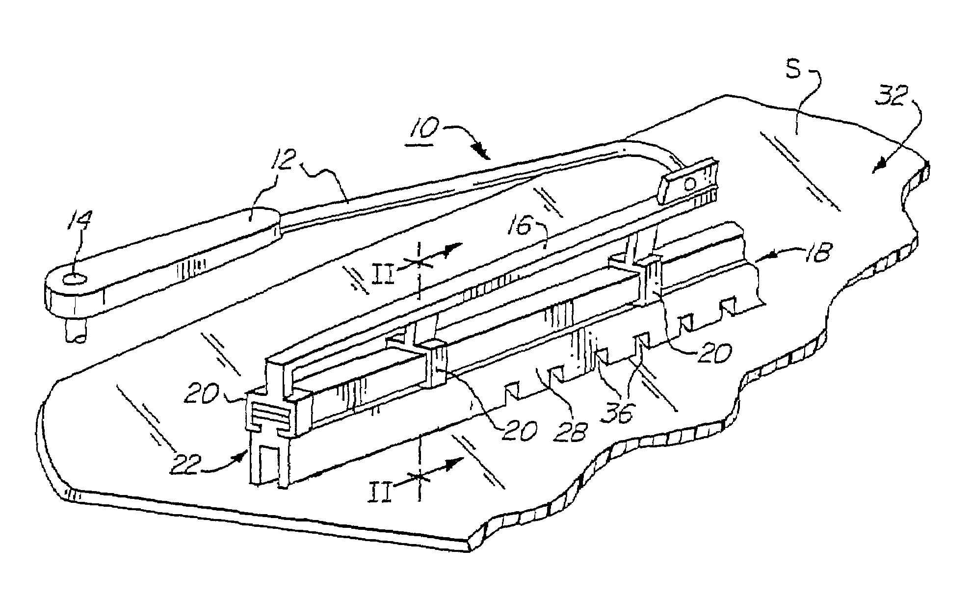
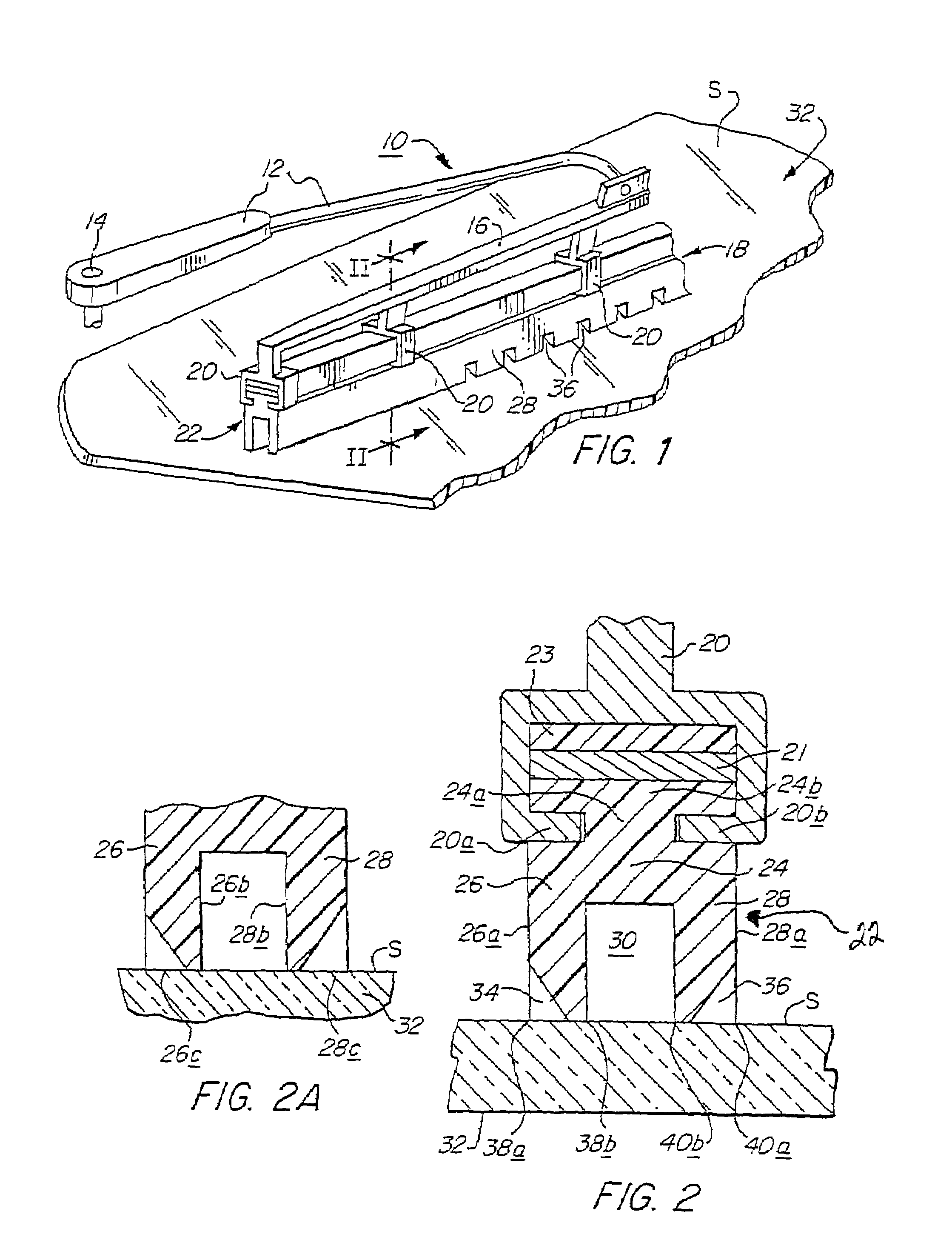
[0040]Referring now to FIG. 1, a windshield wiper assembly is generally indicated at 10 and comprises an arm 12, one end of which is mounted on a support head 14, which is a standard item on motor vehicles, and rotates in alternate opposite directions to traverse bridge arm 16 on which is carried a wiper fixture 18. Wiper fixture 18 is carried on bridge arm 16 by a series of clips 20 which retain a wiper 22 which is wiped across the exterior surface S of wind-shield 32.

[0041]Referring now to FIG. 2, wiper 22 has a central portion 24 which is connected by neck 24a to head 24b, a first blade 26 and a second blade 28. Neck 24a is formed by a pair of opposite grooves (unnumbered) within which are received opposite arms 20a, 20b of a plurality of clips 20. Clips 20 may be made of any suitable material, such as alumi...


PUM


Abstract

A wiper (22) has a length (L) which is divided into a distal segment (D), a middle segment (M) and a proximal segment (P). Wiper (22) has first and second wiper blades (26, 28), each having wiping faces (26c, 28c) in contact with a surface S and defining therebetween a channel (30). One or both of the blades (26, 28) have one-way water-passage formations thereon along the middle segment (M) of the length (L) thereof. Such formations, e.g., notches (34,36), are dimensioned and configured to permit passage of water through, e.g., the second blade (28), to the channel (30) when the second blade (28) is moving in a first direction, and to prevent passage of water through notches (34) when the second blade is moving in a second direction opposite to the first direction. Conversely, the first blade (26) formations, e.g., notches (34), permit water to pass through the formations when the first blade (26) is moving in the second direction and to prevent passage of water therethrough when the first blade is moving in the first direction. At least one intermediate blade (27) may be disposed between the first and second blades (26, 28) to divide the channel (30) into a first course (30a) and a second course (30b). A method of wiping a surface (S) includes controlled entry of water into the channel (30) and expulsion of water from the distal end (42) of the channel, assisted by a Venturi Effect and centrifugal force.

Description

CROSS-REFERENCE TO RELATED APPLICATIONS[0001]This application is a continuation-in-part of application Ser. No. 09 / 714,880, filed Nov. 16, 2000, in the name of Albert J. James and entitled “Water-Diverting Windshield Wiper Blades”, now U.S. Pat. No. 6,618,895, which is a continuation-in-part of application Ser. No. 09 / 631,071, filed Aug. 2, 2000, in the name of Albert J. James and entitled “Water-Diverting Windshield Wiper and Method of Use”, which has been abandoned.BACKGROUND OF THE INVENTION[0002]1. Field of the Invention[0003]This invention relates generally to reciprocating wipers, e.g., windshield wipers, and, specifically, to windshield wipers having two or more blades which have formations therein which permit flow of liquid, e.g., water, through the blades in one direction of movement of the wiper, but not in the other.[0004]2. Related Art[0005]Known wipers usually comprise one or more resilient rubber blades mounted on an arm which reciprocatingly sweeps the blades sideway...

Claims


Application Information

Patent Timeline
Patent Type & Authority Patents(United States)
IPC IPC(8): B60S1/38
CPCB60S1/3801B60S2001/3837B60S2001/3836B60S2001/3829
Inventor JAMES, ALBERT J.
Owner JAMES ALBERT J
Learn More