
Induction heating device, induction heating fixing device and image forming apparatus

a technology of fixing device and demagnetizing coil, which is applied in the direction of electric/magnetic/electromagnetic heating, instruments, electrographic processes, etc., can solve the problems of enlargement of the device, the inability to achieve the effective function of the demagnetizing coil, etc., and achieve compact configuration, increased stability and safety in control

Active Publication Date: 2006-02-28
KONICA MINOLTA BUSINESS TECH INC
View PDF5 Cites 20 Cited by
  • Summary
  • Abstract
  • Description
  • Claims
  • Application Information

AI Technical Summary

Benefits of technology

"The present invention provides an induction heating device and an induction heating fixing device that can improve stability and safety in controlling the temperature of an object to be heated. The device includes an exciting coil and a demagnetizing coil positioned along the object to be heated, with the demagnetizing coil positioned between the exciting coil and the object. The demagnetizing coil can be cooled by air, resulting in improved stability and low cost. The device can be used in an image forming apparatus and can effectively control the temperature of the object being heated. The technical effects of the invention include improved stability and safety in controlling the temperature of the object, compactness, and low cost."

Problems solved by technology

In such an arrangement in which the demagnetizing coils extend in the direction perpendicular to the layers of the exciting coil as in the patent literatures, however, the exciting coil and most of the demagnetizing coils (portions of the demagnetizing coils other than end portions on the side of the exiting coil) are so apart from each other that leakage flux (magnetic flux that is produced by the exciting coil and that does not contribute to the induced current in the heating roller) misses the demagnetizing coils, and effective function of the demagnetizing coils is thereby prohibited.
In addition, there is a problem in that increase in vertical size of the magnetic cores results in enlargement of the device.

Method used


Image

  • Induction heating device, induction heating fixing device and image forming apparatus
  • Induction heating device, induction heating fixing device and image forming apparatus
  • Induction heating device, induction heating fixing device and image forming apparatus

Examples


Embodiment Construction

[0081]Hereinbelow, the present invention will be described in detail with reference to embodiments shown in the drawings.

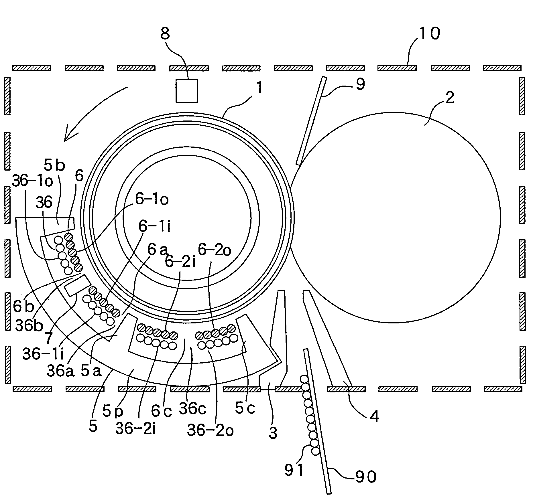
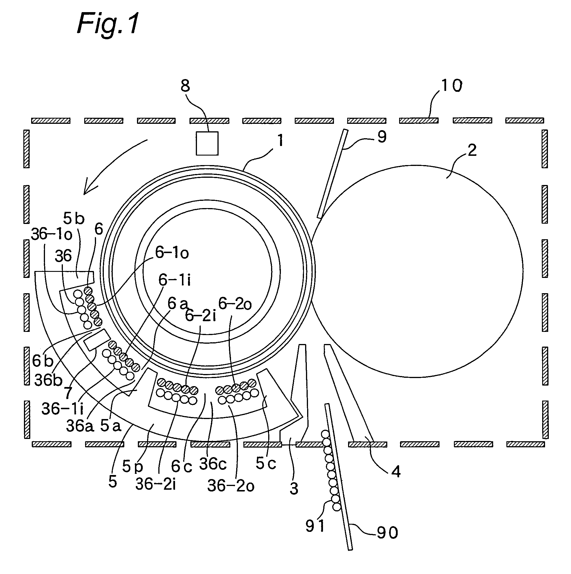
[0082]FIG. 1 shows a sectional configuration of a fixer for color laser printer as one embodiment of an induction heating fixing device having an induction heating device of the invention.

[0083]The fixer has in a casing 10 a cylindrical fixing roller 1 as an object to be heated or a fixing member, a cylindrical pressurizing roller 2 as a pressurizing member, a ferrite core 5 as a holder, a layer-like exciting coil 6 that is positioned so as to extend along outer periphery of the fixing roller 1, a layer-like demagnetizing coil 36 that is interposed between the exciting coil 6 and the ferrite core 5, a first temperature sensor 7 composed of a thermostat, a second temperature sensor 8 of infrared type, and guides 3, 4, and 9 for guiding a paper form 90 as a sheet.

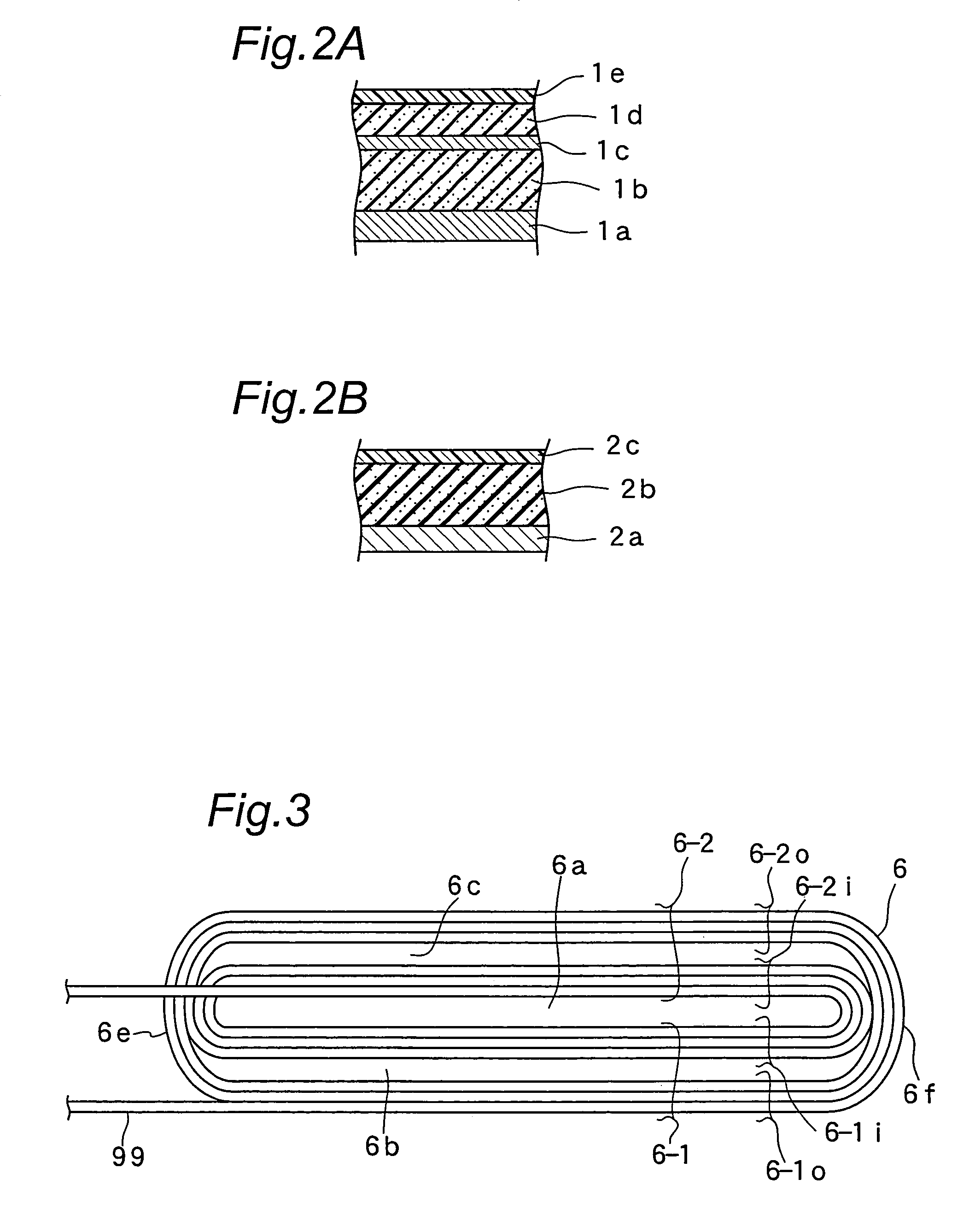
[0084]As shown in FIG. 2A, the fixing roller 1 is composed of a 1-mm-thick core metal 1a made of iron on...


PUM


Abstract

An induction heating device for inductively heating an object to be heated which is formed of conductive material has a holder. The holder is positioned outside the object. The device has an exciting coil for inductively heating the object. The exciting coil is supported by the holder. The exciting coil is composed of a plurality of turns of conductor forming a layer, which is positioned along the object. The device also has a demagnetizing coil which is positioned along the layer of the exciting coil. In the demagnetizing coil, a back electromotive force is induced in accordance with a magnetic field produced by the exciting coil, so as to cancel the magnetic field. Stability in the temperature control for the object such as a heating roller can be improved by effective function of the demagnetizing coil. The device can be miniaturized and configured at low cost.

Description

[0001]This application is based on an application No.2003-339756 filed in Japan, the contents of which are hereby incorporated by reference.BACKGROUND OF THE INVENTION[0002]The present invention relates to an induction heating device for inductively heating an object to be heated which is formed of conductive material.[0003]The invention also relates to an induction heating fixing device of induction heating type for fixing to a sheet a toner image formed on the sheet while conveying the sheet.[0004]The invention also relates to an image forming apparatus having an image forming unit for forming a toner image on a sheet and an induction heating fixing device of induction heating type for fixing to the sheet the toner image formed on the sheet while conveying the sheet having the toner image formed thereon by the image forming unit. Among image forming apparatus of this type are copying machines, laser printers, facsimiles and the like, typically.[0005]In a typical fixing device of i...

Claims


Application Information

Patent Timeline
Patent Type & Authority Patents(United States)
IPC IPC(8): H05B6/14G03G15/20H05B6/40H05B6/44
CPCH05B6/145
Inventor FUJIITANINO, KENOHNO, YASUHIROMIYAZAKI, MASAMI
Owner KONICA MINOLTA BUSINESS TECH INC
Learn More