
Retractable lifting blades for aircraft

a technology of retractable blades and aircraft, which is applied in the direction of aircraft, rotorcraft, vehicles, etc., can solve the problems of limiting the top speed, affecting the flight speed, and affecting the helicopter's limitations, so as to reduce the length of the lifting surface of each blade, the effect of increasing the length

Active Publication Date: 2006-02-28
GERBINO ALLEN J
View PDF16 Cites 17 Cited by
  • Summary
  • Abstract
  • Description
  • Claims
  • Application Information

AI Technical Summary

Benefits of technology

[0005]In one embodiment of the invention, a rotor blade assembly for providing vertical lift to an aircraft is disclosed, having a rotor head, a plurality of cam surfaces, a plurality of blades, with each blade attached to a cam surface, whereby movement of a cam surface causes the radial distance between the distal tip of the attached blade and the center of the rotor head to alter. In this way, the length of the lifting surface of each blade can be decreased or increased. In the preferred embodiment, the blades are moved from a fully extended position providing maximum lift, to a fully retracted stowed or parked position, in which the blades are completely removed from the airstream.

Problems solved by technology

One of the main limitations of rotorcraft aircraft is the flight speed limitation caused by the physics and mechanics of flight.
These limitations have plagued the helicopter since its conception.
Retreating blade stall, dissymmetry of lift, leading, lagging, flapping and coning are just some of the forces that limit the top speed of helicopters.
For example, most helicopters are limited to air speeds of less than 200 miles an hour.

Method used


Image

  • Retractable lifting blades for aircraft
  • Retractable lifting blades for aircraft
  • Retractable lifting blades for aircraft

Examples


Embodiment Construction

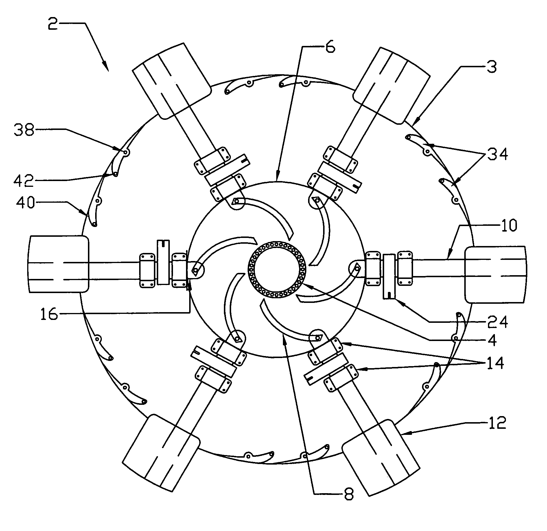
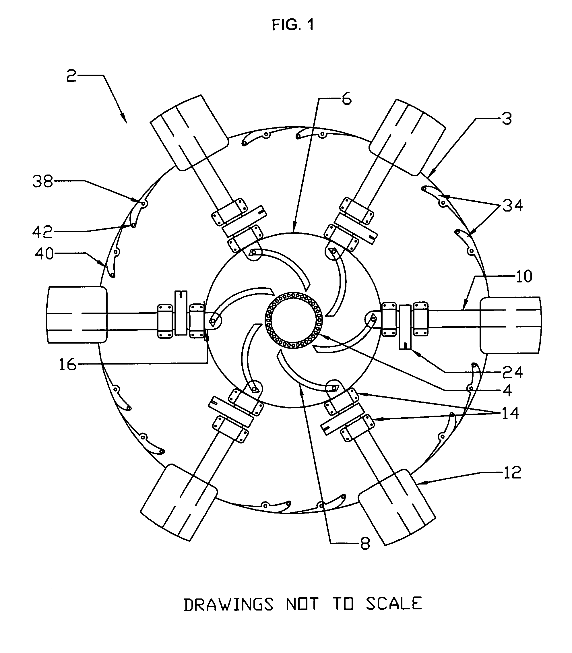
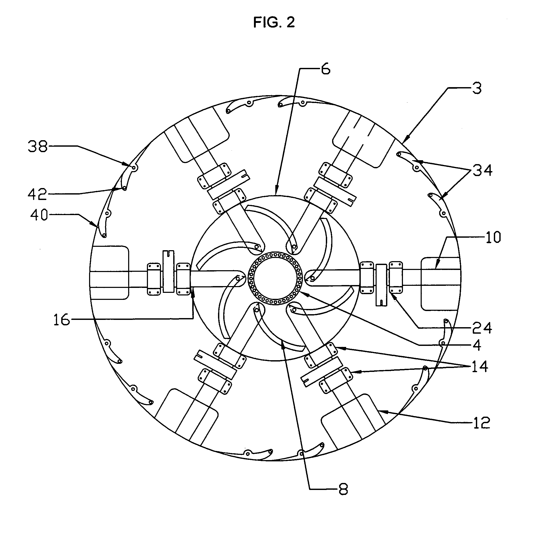
[0043]A rotor head assembly 2 of the preferred embodiment is depicted in FIG. 1. The figure is not to scale. FIG. 1 depicts the condition of a helicopter in flight with the blades fully extended. This figure is a view from the top of the helicopter. The basic components are as follows. At the center of the drawing is depicted the hollow mast 4, which in the preferred embodiment is a standard helicopter mast. The drive shaft (not shown) is within the mast. Around the mast 4 are the rotor head bearings (not shown in this view) supporting the rotor head assembly 2. In turn, the operating cam 6 is bearing mounted (not shown in this view) on the rotor head 3 and can be rotated relative to the mast 4 and the rotor head assembly 2. Cam grooves 8 are shown, in which are mounted the proximal ends of the blade spars 10. The drawing shows one means of deploying the blades 12, utilizing cam grooves 8 having one particular configuration, but the grooves may be longer or shorter, have a deeper or...


PUM


Abstract

A rotor blade assembly for providing vertical lift to an aircraft, having a rotor head and a plurality of blades, with each blade attached to a mechanism such as a cam surface, whereby movement of the mechanism causes the radial distance between the distal tip of the attached blade and the center of the rotor head to alter, decreasing or increasing the length of the lifting surface. The blades are moved from a fully extended position providing maximum lift, to a retracted position in which the blades are removed from the airstream. The pitch of the blades may be controlled to achieve full helicopter responsiveness. A plurality of bladeletts may be positioned near the outer periphery of the rotor head. When they are moved into the airstream, passing air impacts the bladeletts exerting a pressure, causing rotational movement of the rotor blade assembly.

Description

CROSS-REFERENCE TO RELATED APPLICATIONS[0001]This application claims benefit of the prior filing date of U.S. provisional patent application No. 60 / 409,582 filed on Sep. 9, 2002, herein incorporated by reference in its entirety.FIELD OF THE INVENTION[0002]The invention is generally described as a rotorcraft type rotor-head having retractable blades, which may be fitted to either a fixed-wing or rotorcraft aircraft.BACKGROUND OF THE INVENTION[0003]One of the main limitations of rotorcraft aircraft is the flight speed limitation caused by the physics and mechanics of flight. These limitations have plagued the helicopter since its conception. Retreating blade stall, dissymmetry of lift, leading, lagging, flapping and coning are just some of the forces that limit the top speed of helicopters. For example, most helicopters are limited to air speeds of less than 200 miles an hour. The present invention, the Gerbino Flight System, allows fixed wing aircraft to be lifted vertically and then...

Claims


Application Information

Patent Timeline
Patent Type & Authority Patents(United States)
IPC IPC(8): B64C27/52B64C27/30B64C27/50
CPCB64C27/50B64C27/30
Inventor GERBINO, ALLEN J.
Owner GERBINO ALLEN J
Learn More