
Method of achieving timing closure in digital integrated circuits by optimizing individual macros

a timing closure and optimization technique technology, applied in the field of design and automation thereof, can solve the problems of imperfect apportioning process, interfering with the achievement of overall timing closure, and affecting the overall timing closure, so as to improve not only the arrival time, but also the overall timing closure

Inactive Publication Date: 2006-02-21
GLOBALFOUNDRIES INC
View PDF10 Cites 15 Cited by
  • Summary
  • Abstract
  • Description
  • Claims
  • Application Information

AI Technical Summary

Benefits of technology

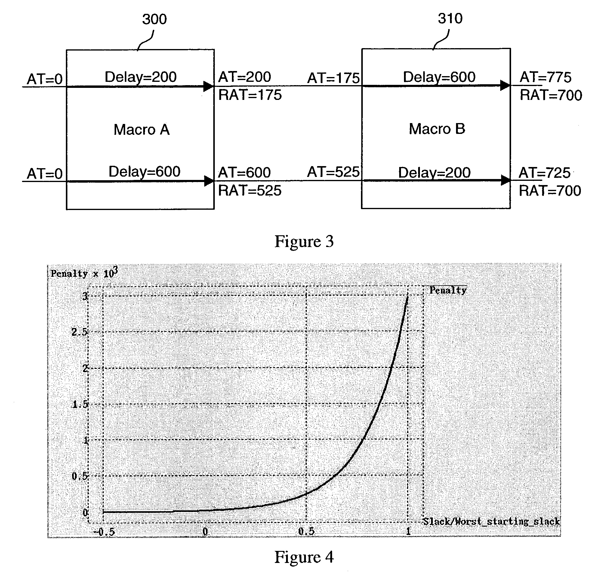
The invention is a method for improving timing closure during the design process of a system. Instead of focusing only on the most critical signals, the method encourages automatic optimization to improve the arrival time of every output signal, based on its criticality. This approach leads to more efficient and effective overall timing closure.

Problems solved by technology

Achieving timing closure is an important, iterative and time-consuming step in the design of any digital integrated circuit.
More typically, the apportionment process is imperfect and involves some conjecture and guesswork.
The main difficulty in prior-art techniques is that the application of automatic optimization techniques on individual macros interferes with the achievement of overall timing closure.
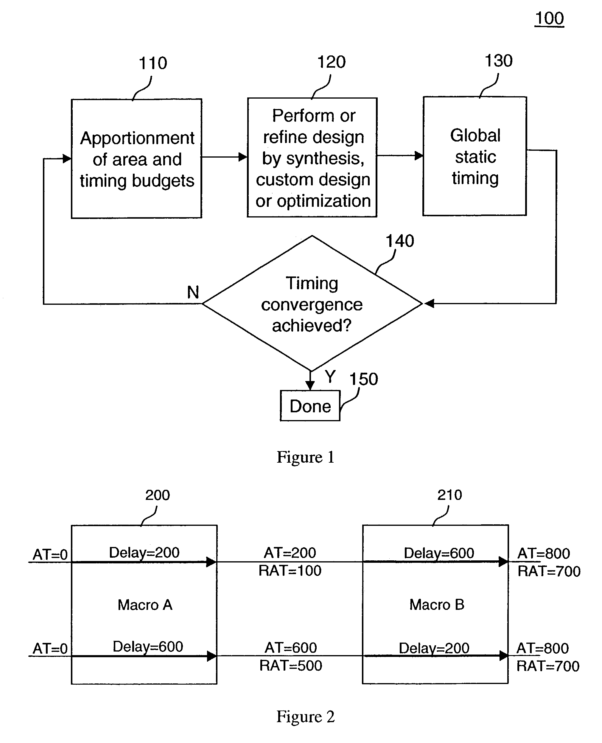
Unfortunately, prior-art methods will never achieve timing closure in this case, since the redesign and re-optimization of individual macros typically target the worst slack, and because the short paths cannot be improved, the redesign and re-optimization techniques have no incentive to improve the delay of the long paths.
Again, prior-art methods will never achieve timing closure under this apportionment scheme, since the redesign and re-optimization of individual macros typically target the worst slack, and because the long paths cannot be improved beyond 550, the redesign and re-optimization techniques have no incentive to improve the delay of the short paths, and upon successive iterations through loop of FIG. 1, the delays and targets will be adjusted by decreasing amounts, and will asmyptotically approach but not reach timing closure.
The reason is that the short path's stubborn negative slack at each iteration of FIG. 1 will limit the improvement that is targeted for the long path of each macro.
Irrespective of the apportionment method employed, the crux of the problem is that prior-art optimization techniques target only paths with the worst slack and therefore do not improve sub-critical slacks even though such actions would help achieve timing closure from a global vantage point.
Thus the formulation of the objective function during individual macro optimization has the unwanted consequence of preventing or impeding overall timing convergence.
With a large number of macros and a large number of interconnections between them, the problem is exacerbated and achievement of timing closure becomes an extremely hard problem, leading to costly redesign efforts and increased time-to-market of the product.

Method used


Image

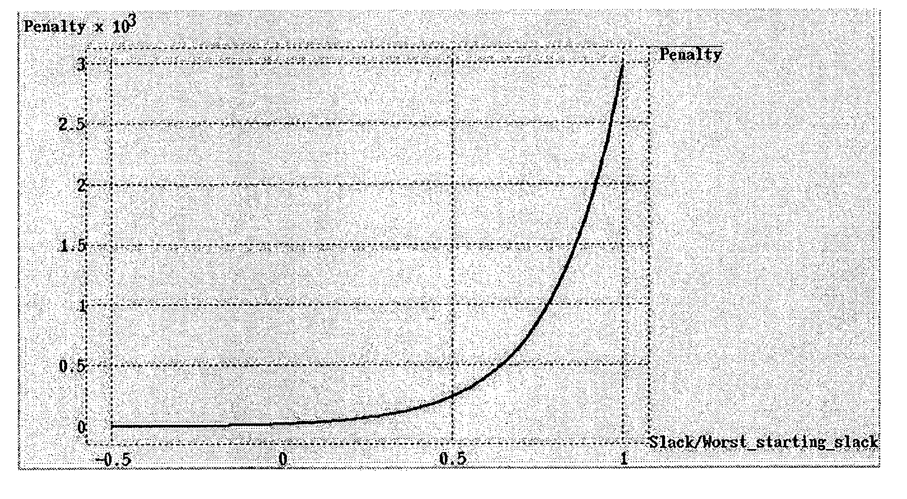
  • Method of achieving timing closure in digital integrated circuits by optimizing individual macros
  • Method of achieving timing closure in digital integrated circuits by optimizing individual macros
  • Method of achieving timing closure in digital integrated circuits by optimizing individual macros

Examples


Embodiment Construction

[0024]The heart of the invention is the reformulation of the objective function of any optimization that is performed by automatic means to improve individual macros. The reformulation makes the overall timing closure loop more effective and efficient. Traditional circuit optimization tools such as EinsTuner formulate the optimization problem in one of two ways, as described below. A description of EinsTuner is available in A. R. Conn, I. M. Elfadel, W. W. Molzen, Jr., P. R. O'Brien, P. N. Strenski, C. Visweswariah and C. B. Whan, “Gradient-based optimization of custom circuits using a static-timing formulation,” Proceedings of the 1999 Design Automation Conference, June 1999, pages 452–459. The description below assumes a simple combinational circuit to illustrate the detailed description of the invention. It is to be understood that the formulation can easily be extended to situations containing sequential elements including all types of latches and possibly multiple clocks by one...


PUM


Abstract

Disclosed is a method for enhanced efficiency and effectiveness in achieving timing closure of large, complex, high-performance digital integrated circuits. Circuit macros are re-optimized and re-tuned in the timing closure loop by means of a reformulated objective function that allows the optimizer to improve the slack of all signals rather than just the most critical one(s). The incentive to improve the timing of a sub-critical signal is a diminishing function of the criticality of the signal. Thus all signals are improved during the optimization, with the highest incentive to improve on the most critical signals, leading to faster and more effective overall timing closure.

Description

RELATED APPLICATIONS[0001]D. J. Hathaway, L. K. Lange, C. Visweswariah and P. M. Williams, “Method of optomizing and alalyzing selected portions of a digital integrated circut,” filed may 12, 2003 under U.S. Ser. No. 10 / 436,213. E. K. Cho, D. J. Hathaway, M. Hsu, L. K. Lange, G. A. Northrop, C. Visweswariah, C. Washburn, P. M. Williams, J. Zhou, “A Method for Tuning a Digital Design for Synthesized Random Logic Circuit Macros in a Continuous Design Space with Optimal Insertion of Multiple Threshold Voltage Devices,” filed as a continuation in part claiming priority U.S. Ser. No. 10 / 436,213 of May 12, 2003 under U.S. Ser. No. 10 / 842,589.FIELD OF THE INVENTION[0002]This invention relates to the design, and automation thereof, of high-performance digital integrated circuits. The invention is particularly directed to the problem of obtaining timing closure of entire integrated circuits or functional units of an integrated circuit by optimizing or tuning individual macros that constitute...

Claims


Application Information

Patent Timeline
Patent Type & Authority Patents(United States)
IPC IPC(8): G06F17/50G06F9/45
CPCG06F17/5031G06F17/505G06F2217/84G06F30/3312G06F30/327G06F2119/12G06F30/3315
Inventor ZHOU, JUNHATHAWAY, DAVID J.VISWESWARIAH, CHANDRAMOULIWILLIAMS, PATRICK M.
Owner GLOBALFOUNDRIES INC
Learn More