
Tracking a non-posted writes in a system using a storage location to store a write response indicator when the non-posted write has reached a target device

a non-posted write and target device technology, applied in the field of processors, can solve the problems of not providing a means for the processor, the latency of the writes to reach the target device may not be predictable, and exceed the specified amount of tim

Active Publication Date: 2006-02-21
AVAGO TECH INT SALES PTE LTD
View PDF13 Cites 40 Cited by
  • Summary
  • Abstract
  • Description
  • Claims
  • Application Information

AI Technical Summary

Benefits of technology

The patent describes an apparatus and method for detecting and responding to write requests. The apparatus includes a storage location that stores a write response indicator to indicate the reception of a write response. The write response indicator is updated when a write response is received. The technical effect of this invention is to provide a reliable way to detect and respond to write requests, ensuring that data is properly stored and utilized.

Problems solved by technology

Thus, the instruction set of the processor does not, itself, provide a means for determining when the write has reached the target device.
Thus, the latency of the writes to reach the target device may not be predictable, and may in some cases exceed the specified amount of time.
Thus, the software may issue subsequent reads or writes before the given write reaches the target device.
However, not all systems guarantee that reads and writes will be processed (and reach the target device) in the order issued.
Thus, this mechanism may not ensure that the write has reached the target device.

Method used


Image

  • Tracking a non-posted writes in a system using a storage location to store a write response indicator when the non-posted write has reached a target device
  • Tracking a non-posted writes in a system using a storage location to store a write response indicator when the non-posted write has reached a target device
  • Tracking a non-posted writes in a system using a storage location to store a write response indicator when the non-posted write has reached a target device

Examples


Embodiment Construction

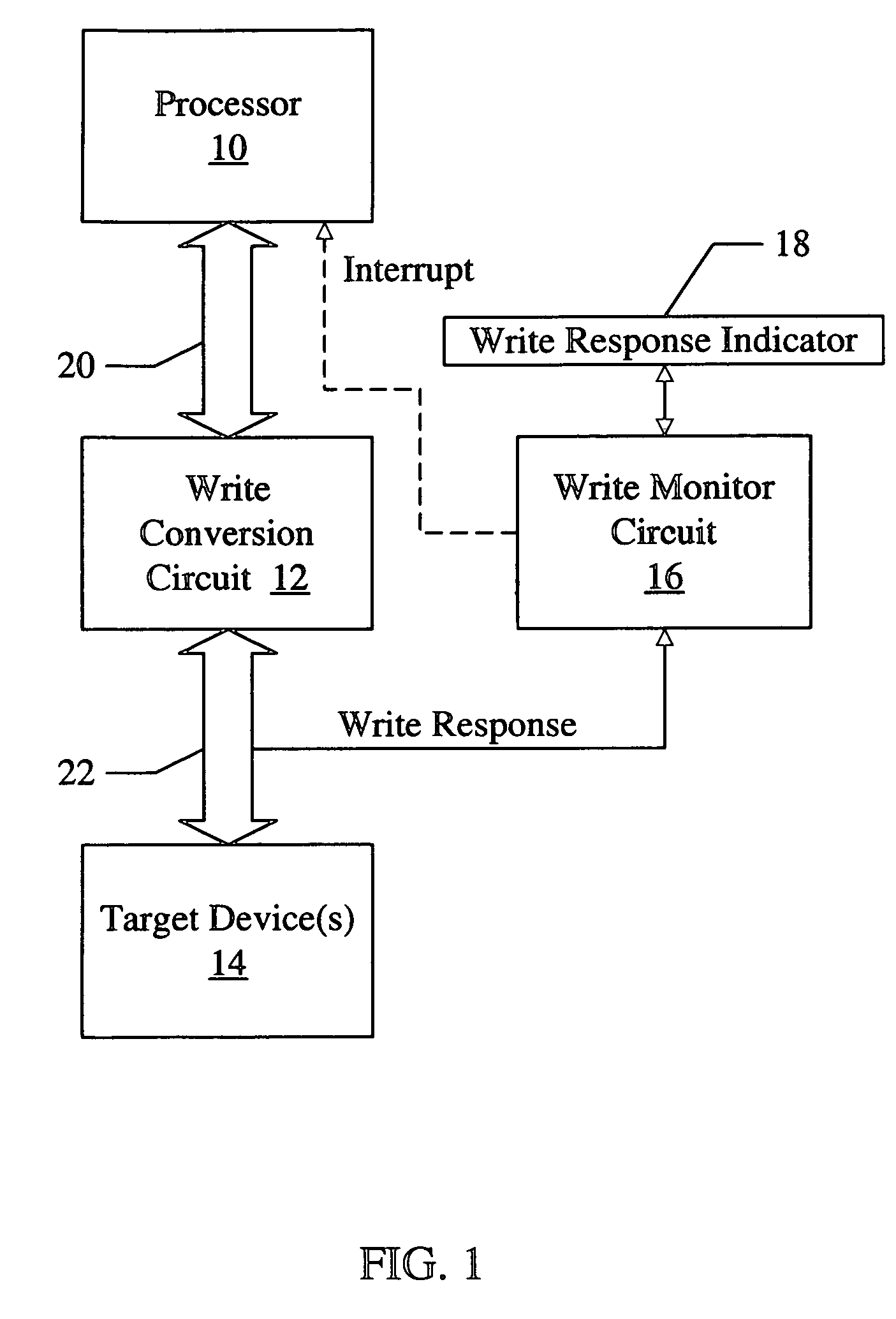
[0021]Turning now to FIG. 1, a block diagram of one embodiment of an apparatus for tracking writes in a system is shown. Other embodiments are possible and contemplated. In the embodiment of FIG. 1, the apparatus includes at least one processor 10, a write conversion circuit 12, a target device or devices 14, a write monitor circuit 16, and a storage location 18. The processor 10 is coupled, via a first interconnect 20, to the write conversion circuit 12, which is further coupled, via a second interconnect 22, to the target device 14. The write monitor circuit 16 is coupled to receive a write response indication (“write response” in FIG. 1). The write monitor circuit 16 is further coupled to the storage location 18, which is configured to store a write response indicator. The write monitor circuit 16 may optionally, in some embodiments, be coupled to interrupt the processor 10 (“interrupt” in FIG. 1) either directly or indirectly.

[0022]Generally, the processor 10 may initiate one or...


PUM


Abstract

An apparatus includes a storage location and a write monitor circuit coupled to the storage location. The storage location is configured to store a write response indicator which is capable of indicating a reception of at least one write response. Each write response indicates that a corresponding write has reached a target device of that write. The write monitor circuit is configured to update the write response indicator in response to receiving an indication of a first write response. A computer accessible medium may comprises instructions which, when executed: (i) initialize the write response indicator; and (ii) issue one or more writes to a target device, wherein the target device is configured to response to each of the writes with a write response to be indicated by the write response indicator.

Description

BACKGROUND OF THE INVENTION[0001]1. Field of the Invention[0002]This invention is related to the field of processors and systems employing processors, and more particularly to tracking non-posted writes in such systems.[0003]2. Description of the Related Art[0004]A processor typically uses read and write transactions (generated in response to load and store instructions, respectively, in the software executing on the processors) to communicate with various devices included in the system with the processor. Among other things, the reads and writes may be used to configure the devices (e.g. during initial bring up of the system), to change the configuration during operation, to control the devices, to generally communicate with the devices, etc.[0005]In some cases, the software may need to be able to determine whether or not certain writes have reached the target device. For example, “device driver” software (which is typically coded specifically for the target device, to directly int...

Claims


Application Information

Patent Timeline
Patent Type & Authority Patents(United States)
IPC IPC(8): G06F13/36G06F13/42
CPCG06F13/4217
Inventor CHUI, KWONG-TAK A.GO, SHUN WAIHAYTER, MARK D.NING, CHUN H.SILVERIA, AMY K.
Owner AVAGO TECH INT SALES PTE LTD
Learn More