
Load storage apparatus

a technology of storage apparatus and load, applied in the direction of instruments, furniture, programme control, etc., can solve the problems of fixed errors in horizontal and/or vertical accuracy of the rack, delicate or slightly different, and the size of the rack, so as to achieve automatic and efficient learning a proper

Inactive Publication Date: 2006-02-21
DAIFUKU CO LTD
View PDF11 Cites 43 Cited by
  • Summary
  • Abstract
  • Description
  • Claims
  • Application Information

AI Technical Summary

Benefits of technology

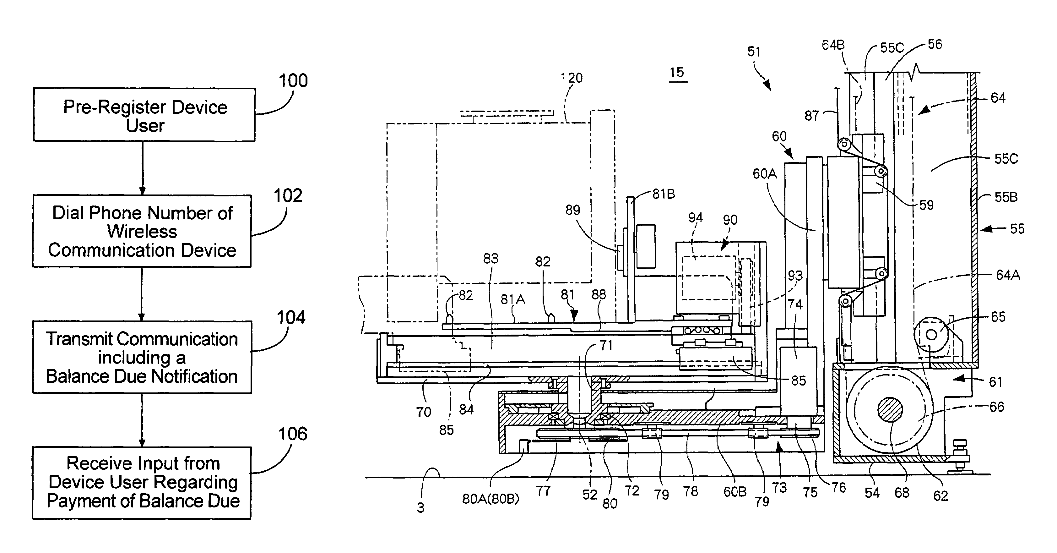
[0008]In view of the foregoing problems, it is the object of the present invention to provide a load storage apparatus that can automatically and efficiently learn a proper distance for which the carrier of the transferrer moves relative to each load support of the rack, and can safely and normally load and unload the load support on the basis of the learned value.

Problems solved by technology

In this case, initial errors in size of the rack, installation or fixation errors in horizontal and / or vertical accuracy of the rack, and / or other errors may delicately or slightly vary the positions of the positioning pins of the shelves relative to the carrier of the transferrer and / or the distance between each of the pins and the carrier.
The adjustments require much time and labor, and operators different in skill may make various adjustments.

Method used


Image

  • Load storage apparatus
  • Load storage apparatus
  • Load storage apparatus

Examples


second embodiment

[0119]FIG. 13(a) shows a load storage apparatus according to the present invention. This apparatus includes two rotary racks 21 each having a cylindrical turning path 23, one transferrer 51 having a cylindrical transfer path 53, and two fixed racks 101. The transferrer 51 is positioned between the rotary racks 21. The fixed racks 101 are positioned on the transfer path 53.

third embodiment

[0120]FIG. 13(b) shows a load storage apparatus according to the present invention. This apparatus includes three rotary racks 21 each having a cylindrical turning path 23, one transferrer 51 having a cylindrical transfer path 53, and two fixed racks 101. The transferrer 51 is positioned between two of the rotary racks 21 and side by side with the other rotary rack 21. The fixed racks 101 are positioned on the transfer path 53.

fourth embodiment

[0121]FIG. 13(c) shows a load storage apparatus according to the present invention. This apparatus includes one rotary rack 21 having a cylindrical turning path 23, two transferrers 51 each having a cylindrical transfer path 53, and eight fixed racks 101. The rotary rack 21 is positioned on one side of the position between the transferrers 51. Four of the fixed racks 101 are positioned on each of the transfer paths 53.


PUM


Abstract

The object of the present invention is to provide a load storage apparatus that can automatically and efficiently adjust the distances for which its transferrer moves loads to transfer them. The apparatus may include a rotary rack, fixed racks and a transferrer. Each of the racks may include shelves. The transferrer includes a carrier for transferring cassettes by moving relative to the shelves. The carrier can be fitted with a unit including a photoelectric switch for detecting ends of the shelves. The apparatus measures the distance for which the carrier moves from a reference position toward each of the shelves until the photoelectric switch of the unit on the carrier is activated. The measurement enables the apparatus to learn the distance for which the carrier moves to the position where a cassette can be transferred onto and from each of the shelves. Consequently, it is possible to transfer the cassettes without hindrance even if the cassette-positioning pins of the shelves shift slightly out of position. Additionally, prior to operation of the apparatus, an operator does not need to adjust the distances for which the carrier moves.

Description

BACKGROUND OF THE INVENTION[0001]1. Field of the Invention[0002]The present invention relates to load storage apparatus or equipment for storing loads in a clean room or the like.[0003]2. Brief Description of the Prior Art[0004]A conventional load storage apparatus includes a rack with shelves or other load supports, each of which can support a cassette containing a number of wafers or liquid crystal panels. The shelves have pins for positioning the cassettes supported on the shelves. The cassettes have holes for engaging with the pins. The engagement prevents the cassettes on the shelves from shifting out of position in such a manner that the cassettes cannot be taken normally out of the storage apparatus. The engagement also prevents the cassettes on the shelves from falling due to the vibration of the shelves during the operation of the storage apparatus, or due to an earthquake, for example.[0005]The storage apparatus also includes a transferrer for loading and unloading the rac...

Claims


Application Information

Patent Timeline
Patent Type & Authority Patents(United States)
IPC IPC(8): G06F7/00B65G1/04B65G1/00B65G1/133B65G1/137B65G49/00H01L21/00H01L21/677
CPCH01L21/67259H01L21/67769Y10S414/14B65G1/137
Inventor INUI, YOSHITAKA
Owner DAIFUKU CO LTD
Learn More