Acoustic-propagation-time measuring apparatus
a technology measuring apparatus, which is applied in the direction of specific gravity measurement, using reradiation, instruments, etc., can solve the problems of high accuracy of acoustic propagation time analytic measurement, distance, distance difference (gap), and the inability to accurately inspect the target object b>1/b> with a known sonar device, etc., to achieve the effect of correcting the high-accuracy analytic measurement o
- Summary
- Abstract
- Description
- Claims
- Application Information
AI Technical Summary
Benefits of technology
Problems solved by technology
Method used
Image
Examples
second embodiment
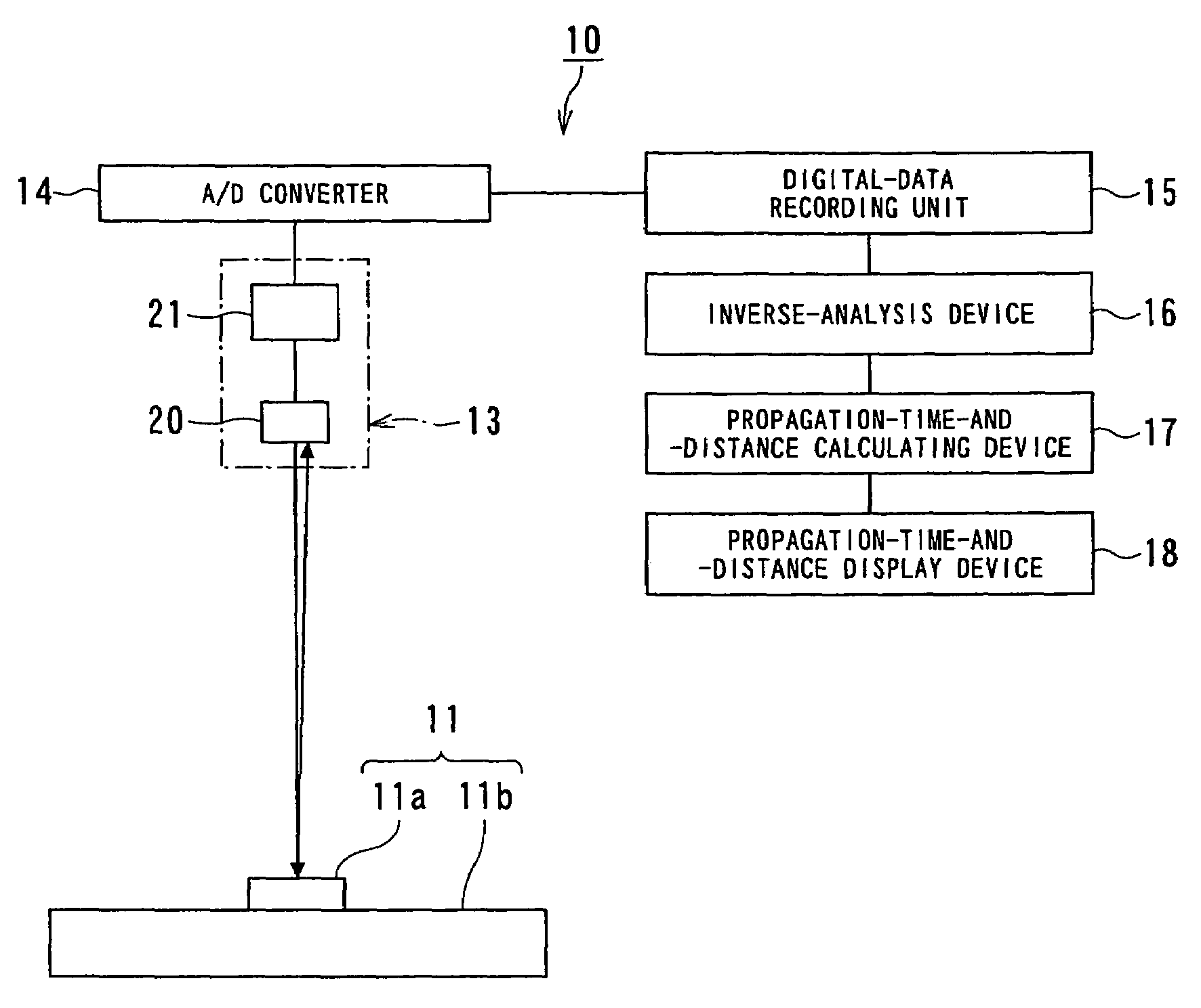
[0075]FIG. 5 is an outline block diagram showing an acoustic-propagation-time measuring apparatus according to the present invention.
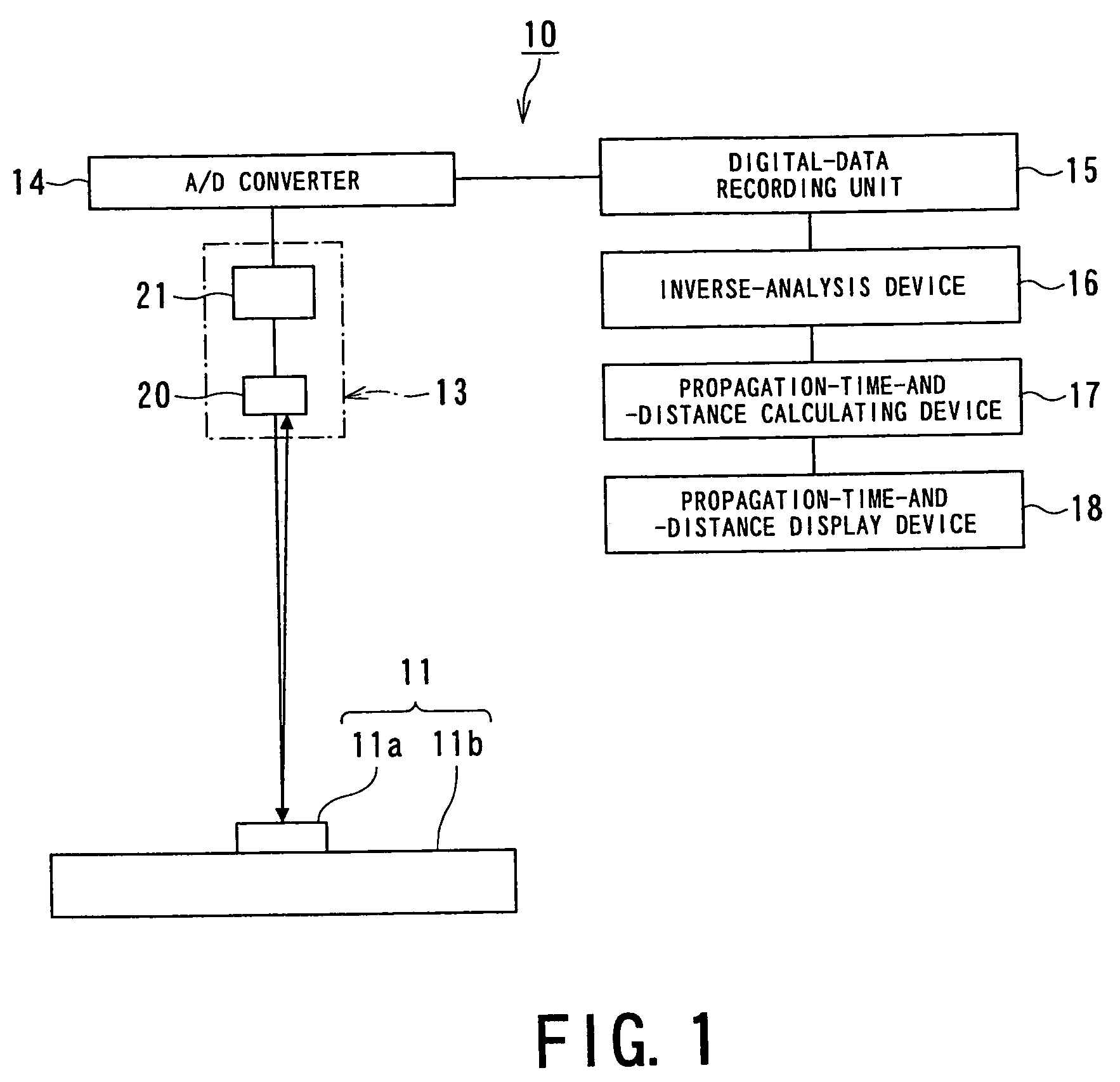
[0076]An acoustic-propagation-time measuring apparatus 10A of this second embodiment basically has the same structure as that of the acoustic-propagation-time measuring apparatus (distance-measuring apparatus) 10 of the first embodiment shown in FIG. 1, except that the acoustic-propagation-time measuring apparatus 10A is provided with a transmitting and receiving device 13A. The same components as those of the acoustic-propagation-time measuring apparatus 10 are denoted by the same reference numerals and will not be described here.
[0077]This acoustic-propagation-time measuring apparatus 10A is applied to a distance-measuring apparatus utilizing acoustic wave, and the transmitting and receiving device 13A includes a plurality pairs of the acoustic element 20 and the emitting and receiving unit 21. An impulse voltage may be applied to the plurality of ac...
third embodiment
[0079]FIG. 6 is an outline block diagram showing an acoustic-propagation-time measuring apparatus according to the present invention.
[0080]An acoustic-propagation-time measuring apparatus 10B according to this third embodiment has basically the same structure as that of the first embodiment shown in FIG. 1, except that the measuring apparatus 10B additionally includes a noise filter 25. The same components as those of the acoustic-propagation-time measuring apparatus 10 are denoted by the same reference numerals and will not be described.
[0081]The noise filter 25 is provided between the digital-data recording unit 15 and the inverse-analysis device 16. With this noise filter 25, noise is eliminated from the digital echo signal E, i.e., an acoustic receiving signal at the signal input end of the inverse-analysis device 16. After the acoustic-propagation-time measuring apparatus 10B is thus made resistive to noise, calculation errors during the inverse analysis can be reduced. Further...
fourth embodiment
[0082]FIG. 7 shows an acoustic-propagation-time measuring apparatus according to the present invention.
[0083]An acoustic-propagation-time measuring apparatus 10C according to this fourth embodiment has basically the same structure as that of the third embodiment shown in FIG. 6, except that the measuring apparatus 10C additionally includes an inverse-analysis correcting device 27. The same components as those of the acoustic-propagation-time measuring apparatus 10B shown in FIG. 6 are denoted by the same reference numerals and will not be described.
PUM
| Property | Measurement | Unit |
|---|---|---|
| frequency | aaaaa | aaaaa |
| frequency | aaaaa | aaaaa |
| gap size | aaaaa | aaaaa |
Abstract
Description
Claims
Application Information
 - R&D
- Intellectual Property
- Life Sciences
- Materials
- Tech Scout
- Unparalleled Data Quality
- Higher Quality Content
- 60% Fewer Hallucinations
Browse by: Latest US Patents, China's latest patents, Technical Efficacy Thesaurus, Application Domain, Technology Topic, Popular Technical Reports.
© 2025 PatSnap. All rights reserved.Legal|Privacy policy|Modern Slavery Act Transparency Statement|Sitemap|About US| Contact US: help@patsnap.com


