
Head for perpendicular magnetic recording with a shield structure connected to the return pole piece

a perpendicular magnetic recording and shield structure technology, applied in the direction of head surface, head with metal sheet core, instruments, etc., can solve the problems of two pancake coils and write disturbance of the read shield, and achieve the effect of reducing the flux flow

Active Publication Date: 2006-02-21
WESTERN DIGITAL TECH INC
View PDF16 Cites 147 Cited by
  • Summary
  • Abstract
  • Description
  • Claims
  • Application Information

AI Technical Summary

Benefits of technology

The design enhances write field strength, reduces partial erasure, improves saturation, and decreases media noise, enabling higher coercive field media stability and sharper transition sharpness.

Problems solved by technology

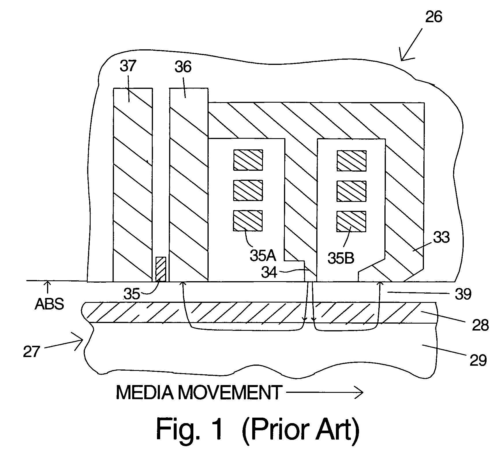
A disadvantage of this design is that it requires two pancake coils.
The figure also shows this design will result in write disturbance of the read shields.

Method used


Image

  • Head for perpendicular magnetic recording with a shield structure connected to the return pole piece
  • Head for perpendicular magnetic recording with a shield structure connected to the return pole piece
  • Head for perpendicular magnetic recording with a shield structure connected to the return pole piece

Examples


Embodiment Construction

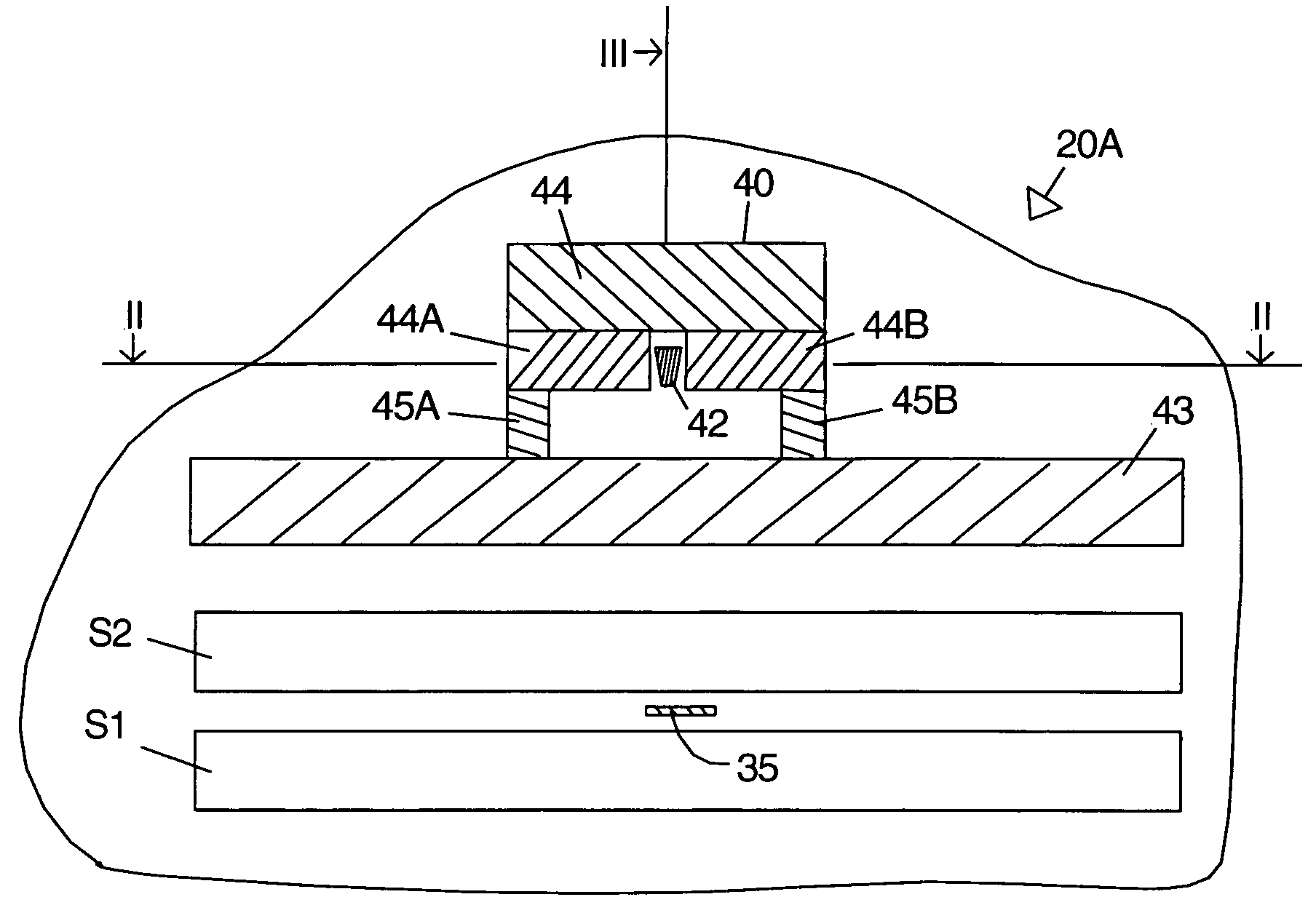
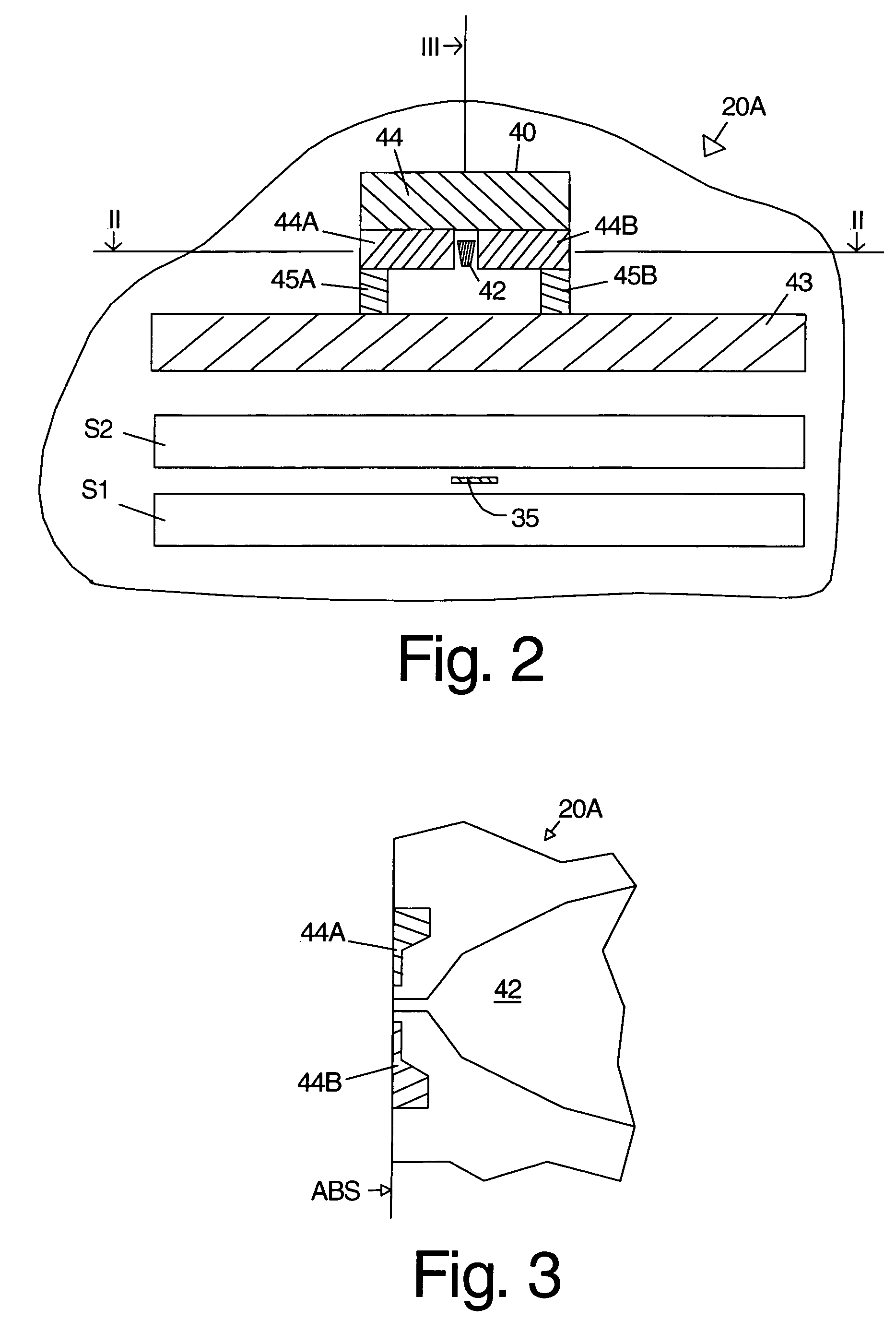
[0017]FIG. 2 is a symbolic illustration of the ABS of a head 20A according to a first embodiment of the invention. This figure and the others included herein are not to scale, in part because the smaller components and spacings would be unclear. Places where the relative sizes and dimensions are significant will be noted if not known to those skilled in the art. The ABS is shown without the thin film protective overcoat which would normally be present in a production head. The term ABS as used herein means the plane as shown in the drawings without regard to whether an overcoat is present. The read sensor 35 and its shields S1, S2 can be located on either side of the write head, i.e., the read head can be fabricated first or last. The ferromagnetic yoke includes main (write) pole piece 42 and return pole piece 43. The shield structure 40 includes the trailing shield 44 and the side shields 44A, 44B. The movement of the magnetic recording medium is from the return pole piece 43 to th...


PUM

PropertyMeasurementUnit
included angle BACaaaaaaaaaa
thicknessaaaaaaaaaa
distanceaaaaaaaaaa

Abstract

An embodiment of the invention is a head for perpendicular recording that has a trailing shield and side shields that are connected to the return pole piece by two studs of ferromagnetic material. The studs extend parallel to the track direction and are located a sufficient distance away from the main pole piece to reduce the flux flow from the main pole piece to the studs. Optionally the studs can be recessed behind the air-bearing surface. The preferred embodiment of the invention is a magnetic transducer with separated read and write heads for perpendicular recording.

Description

FIELD OF THE INVENTION[0001]The invention relates to thin film magnetic transducers for perpendicular recording and more particularly to the inductive write head portion of the transducer and even more particularly to the design of the pole pieces for the inductive write head.BACKGROUND OF THE INVENTION[0002]In a typical prior art magnetic disk recording system a slider containing magnetic transducers for reading and writing magnetic transitions flies above the disk while it is being rotated by a spindle motor. The disk includes a plurality of thin films and at least one ferromagnetic thin film in which the recording (write) head records the magnetic transitions in which information is encoded. The magnetic domains in the media on can be written longitudinally or perpendicularly. The read and write head portions of the slider are built-up in layers using thin film processing techniques. Typically the read head is formed first, but the write head can also be fabricated first. The con...

Claims


Application Information

Patent Timeline
Patent Type & Authority Patents(United States)
IPC IPC(8): G11B5/147G11B5/187G11B5/00G11B5/11G11B5/127G11B5/31
CPCG11B5/11G11B5/1278G11B5/315G11B5/3116G11B2005/0029G11B5/187
Inventor HSU, YIMINLE, QUANGNIX, JAMES LAMARWILLIAMS, MASON LAMAR
Owner WESTERN DIGITAL TECH INC
Learn More