
Compact non-linear geometry electromagnetic coupler for use with digital transmission systems

a digital transmission system and compact technology, applied in logic circuit coupling/interface arrangement, high frequency circuit adaptation, instruments, etc., can solve the problems of reducing the number of system cards that may be attached to and affecting the performance of the high-performance digital system

Inactive Publication Date: 2006-02-21
INTEL CORP
View PDF8 Cites 14 Cited by
  • Summary
  • Abstract
  • Description
  • Claims
  • Application Information

AI Technical Summary

Benefits of technology

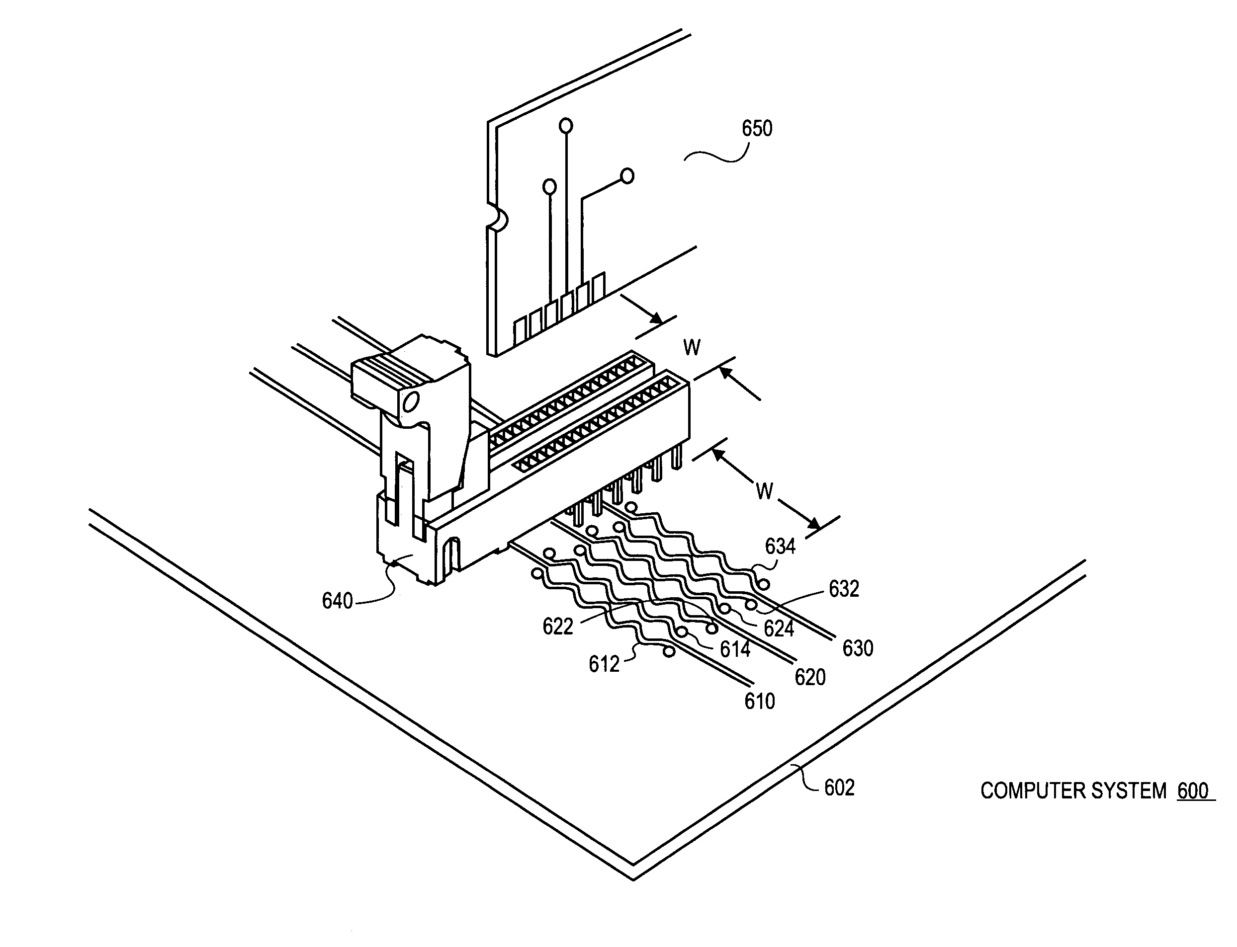
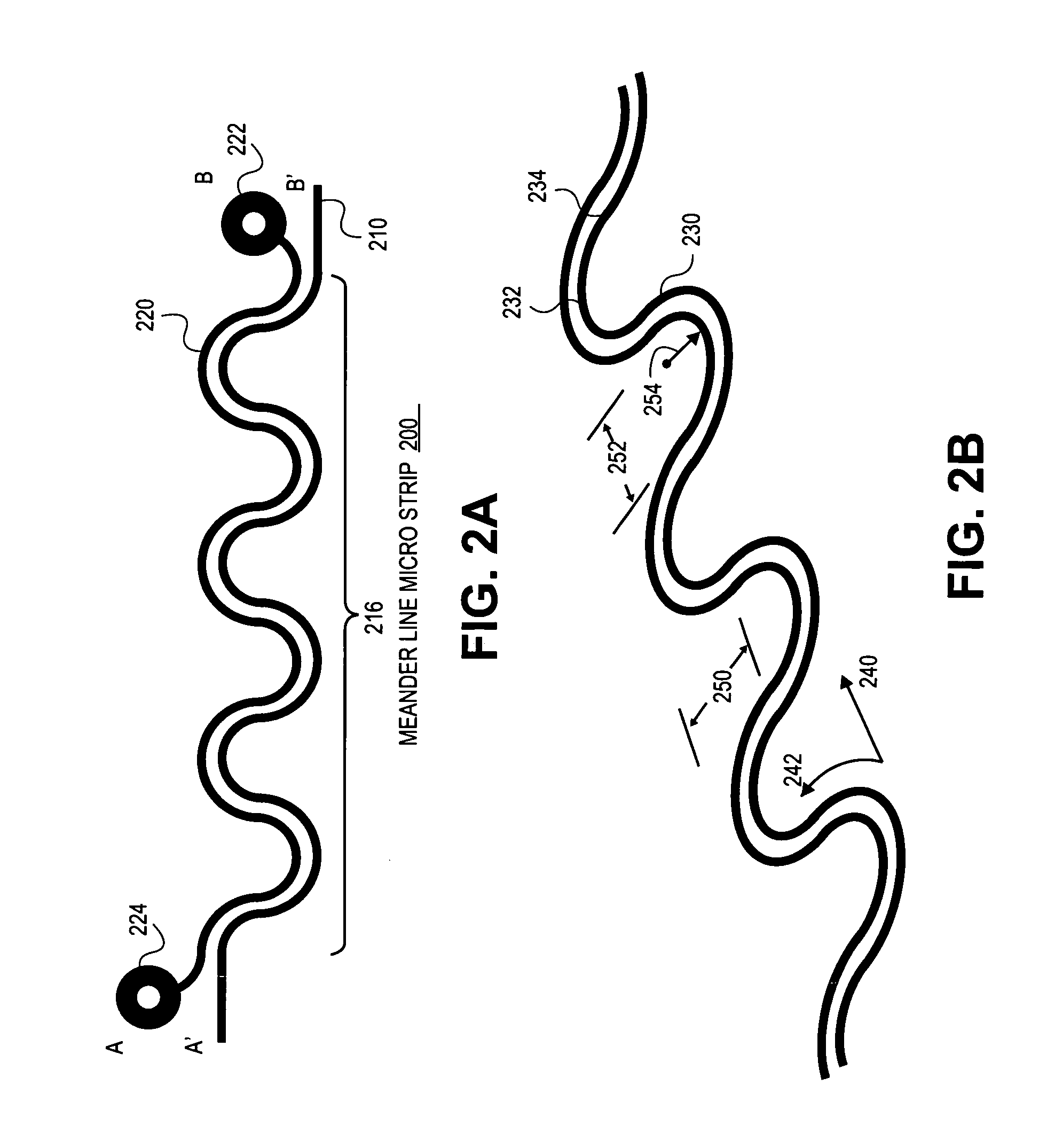
[0016]A compact electromagnetic coupler for use with digital transmission system is described. In one embodiment, the compact electromagnetic coupler includes a first transmission structure, including a portion having a geometry. A second transmission structure having the geometry is positioned proximate the portion of the first transmission line structure having the geometry to form an electromagnetic coupler with the first transmission line structure to enable the reconstruction of a signal transmitted along the first transmission structure.

Problems solved by technology

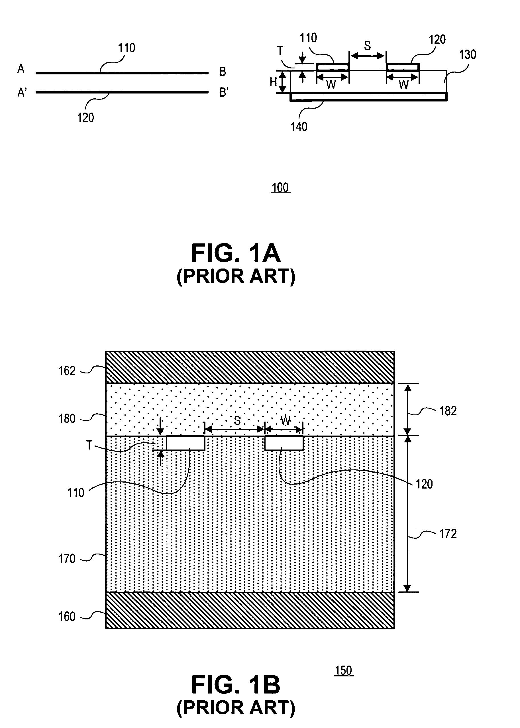
Unfortunately, multi-drop buses are rarely used today in high performance digital systems due to the fact that the stubs severely limit the bandwidth at which the bus can operate.
As a result, transmission line reflections and consequent inter-symbol interference often occurs when operating at high frequencies.
As a result, the number of system cards that may be attached to the high performance digital system is drastically reduced and generally limited to the attachment of only one card, such as for example, a memory card.
In other words, current systems are unable to provide connections for inserting available daughter cards to increasingly high speed mother board memory buses without compromising system performance.

Method used


Image

  • Compact non-linear geometry electromagnetic coupler for use with digital transmission systems
  • Compact non-linear geometry electromagnetic coupler for use with digital transmission systems
  • Compact non-linear geometry electromagnetic coupler for use with digital transmission systems

Examples


Embodiment Construction

[0016]A compact electromagnetic coupler for use with digital transmission system is described. In one embodiment, the compact electromagnetic coupler includes a first transmission structure, including a portion having a geometry. A second transmission structure having the geometry is positioned proximate the portion of the first transmission line structure having the geometry to form an electromagnetic coupler with the first transmission line structure to enable the reconstruction of a signal transmitted along the first transmission structure.

[0017]In the following description, numerous specific details such as logic implementations, sizes and names of signals and buses, types and interrelationships of system components, and logic partitioning / integration choices are set forth in order to provide a more thorough understanding. It will be appreciated, however, by one skilled in the art that the invention may be practiced without such specific details. In other instances, control stru...


PUM


Abstract

A compact electromagnetic coupler for use with digital transmission system is described. In one embodiment, the apparatus includes a first transmission structure, including a portion having a geometry. A second transmission structure having the geometry and positioned proximate the portion of the first transmission line structure having the geometry to form a compact electromagnetic coupler with the first transmission structure a geometry of the electromagnetic coupler to enable placement within a footprint of a standard card connector. The compact electromagnetic coupler so formed enables reconstruction of the logical state and timing of a signal transmitted along the first transmission structure.

Description

FIELD OF THE INVENTION[0001]One or more embodiments of the invention relate generally to the field of electromagnetic coupling devices. More particularly, one or more of the embodiments of the invention relates to a compact electromagnetic coupler for use with digital transmission systems.BACKGROUND OF THE INVENTION[0002]Communication between devices within a computer system is typically performed using one or more buses to interconnect the devices. These buses may be dedicated buses coupling two devices or non-dedicated buses that are multiplexed by a number of units and devices (e.g., bus agents). Moreover, buses within a computer system may be dedicated to transferring a specific path of information. For example, the X86 microprocessor architecture developed by Intel Corporation of Santa Clara, Calif. includes a three bus system with address, data and control buses for respectively transferring data, address and control signals.[0003]A vast amount of research and system architect...

Claims


Application Information

Patent Timeline
IPC IPC(8): H01P5/18G06F13/40H05K1/02
CPCG06F13/4086H01P5/185H05K1/0239H05K2201/10189H05K2201/09236H05K2201/09263H05K2201/044G06F13/40H03K19/0175
Inventor BENHAM, JOHN R.CRITCHLOW, JOHN L.LIANG, TAO
Owner INTEL CORP
Learn More