Apparatus for controlling outdoor unit's louver blades and its method

a technology for outdoor units and apparatuses, which is applied in the direction of domestic cooling apparatus, ventilation systems, heating types, etc., can solve the problems of louver blades which have not been used for a long time, may not be normally operated, and the installation of conventional outdoor units for air conditioners is restricted

Inactive Publication Date: 2006-02-21
LG ELECTRONICS INC
View PDF10 Cites 12 Cited by
  • Summary
  • Abstract
  • Description
  • Claims
  • Application Information

AI Technical Summary

Benefits of technology

[0014]An object of the present invention is to provide an apparatus and method for controlling louver blades of an outdoor unit which can decide a long term non-use state of the louver blades which may interrupt an open / close operation of the louver blades.

Problems solved by technology

However, the conventional outdoor unit for the air conditioner is restricted in installation spaces due to high density and strict environment regulations of cities, and increases civil applications due to noise and heat.
However, an open / close operation of the louver blades 8 is interrupted due to external factors (rain, snow, ice, dust, etc.), and thus the louver blades 8 may not be normally operated after an extended period of time.
In addition, the louver blades which have not been used for a long term may have problems due to the external factors.
As a result, cooling / heating performance of the outdoor unit is rapidly reduced, and thus refrigerants are not efficiently heat exchanged, which has detrimental effects on performance of the indoor unit.
Moreover, when an overload current is transmitted to a driving source for operating the louver blades, the louver blades are closed or a driving member is out of order due to the overload current, to interrupt the operation of the outdoor unit.
In addition, mis-operations of sensors or switches of the outdoor unit are not sensed.
However, when external humidity is low, for example in a sunny day, such an angle increases a fan resistance, to interrupt suction / discharge of air.

Method used


Image

  • Apparatus for controlling outdoor unit's louver blades and its method
  • Apparatus for controlling outdoor unit's louver blades and its method
  • Apparatus for controlling outdoor unit's louver blades and its method

Examples


first embodiment

[0133]FIG. 6 is a structure view illustrating an apparatus for controlling louver blades of an outdoor unit in accordance with the present invention. Referring to FIG. 6, the apparatus includes a louver blade member 100 as shown in FIGS. 4A and 4B, a driving member 200 for opening / closing louver blades 8 of the louver blade member 100 under the control of a microcomputer 90, a first limit switch 91 for continuously transmitting a contact point signal when the louver blades 8 are closed, and the microcomputer 90 for controlling the driving member 200, and receiving the contact point signal from the first limit switch 91.

[0134]The microcomputer 90 includes a memory (not shown) for storing a non-use reference time of the louver blades 8 automatically set or set by the user before the operation of the outdoor unit 10. Here, the non-use reference time is an allowable time for which the louver blades 8 can remain in a close state. If the louver blades 8 are not operated for a long term, a...

second embodiment

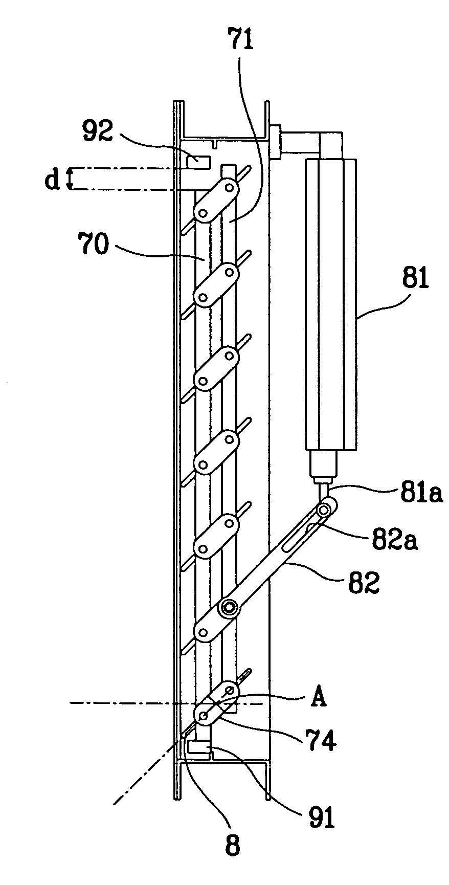
[0148]FIGS. 10A and 10B are side views illustrating a louver blade member and a driving member in close and open states in accordance with the present invention.

[0149]FIG. 10A shows a first limit switch 91 contacting with one end of one of first to fourth levers 70, 71, 72 and 73 (for example, first lever 70), generating a first contact point signal, and continuously transmitting the signal to a microcomputer, and a second limit switch 92 contacting with the other end of the first lever 70, generating a second contact point signal, and continuously transmitting the signal to the microcomputer. The detailed operation will be explained in FIG. 11.

[0150]Referring to FIG. 10B, a driving source 81 (for example, driving motor, hydraulic cylinder, etc.) allows a mover 81a to perform a rectilinear motion in parallel to the first to fourth levers 70, 71, 72 and 73 under the control of the microcomputer, the mover 81a performing the rectilinear motion pushes a connector 82 along a guide groov...

third embodiment

[0163]FIG. 14 is a structure view illustrating an apparatus for controlling louver blades of an outdoor unit in accordance with the present invention. As depicted in FIG. 14, the apparatus includes a louver blade member 100, a driving member 200 for opening / closing the louver blades 8 of the louver blade member 100 under the control of a microcomputer 90, first and second limit switches 91 and 92 for continuously transmitting first and second contact point signals to the microcomputer 90 when the louver blades 8 are closed and opened, and the microcomputer 90 for controlling the driving member 200, and receiving the contact point signals from the first and second limit switches 91 and 92. In addition, the apparatus includes a current transformer 94 connected to the driving member 200, for deciding whether an overload current is generated in a driving source 81 of the driving member 200, generating an overload current generation signal, and transmitting the signal to the microcompute...


PUM


Abstract

An apparatus and method for controlling louver blades of a compressor/condenser unit are provided which can improve efficiency of the compressor/condenser unit based on a position of the louver blades and peripheral conditions. The apparatus includes louver blades with a pair of connecting protrusions formed at each end thereof, and a plurality of levers which are rotatably coupled to the connecting protrusions of the louver blades formed in the same positions. A driving member opens and closes the louver blades by moving the levers, and in turn, the louver blades coupled there to. A microcomputer controls the driving member, and the louver blades are opened and closed based on a control signal from the microcomputer.

Description

TECHNICAL FIELD[0001]The present invention relates to an apparatus and method for controlling louver blades of an outdoor unit, and more particularly to, an apparatus and method for controlling louver blades of an outdoor unit which can improve efficiency of the outdoor unit according to a state of the louver blades and peripheral conditions.BACKGROUND ART[0002]An air conditioner implying a cooler, a heater or both of them is classified into a window type and a split type. In the case of the cooler, a split type air conditioner includes an indoor unit installed indoors for cooling a room, and an outdoor unit connected to the indoor unit through refrigerant pipe lines and installed outdoors to contact air, for performing condensation heat exchange on a refrigerant gas in a condenser by using external air as a cooling medium, and supplying the condensed refrigerants to an evaporator of the indoor unit through the refrigerant pipe lines. The indoor unit is composed of the evaporator fo...

Claims


Application Information

Patent Timeline
Patent Type & Authority Patents(United States)
IPC IPC(8): F25B39/04F24F13/04F24F13/06F24F1/00F24F13/16
CPCF24F1/06F24F1/46F24F13/16F24F1/62F24F1/52F24F11/0015F24F11/30F24F2110/20F24F11/63F24F11/74
Inventor KIM, IN-GYUBAE, YOUNG-JUKOO, JA-HYUNGPARK, BYUNG-IIKIM, KYEONG-HOKIM, YANG-HOHONG, YOUNG-HOHEO, KYEONG-WOOKCHA, KANG-WOOKSUNG, SI-KYONGLEE, DONG-HYUKKANG, SEONG-MINKIM, TAE-GEUN
Owner LG ELECTRONICS INC
Why Eureka
Try Eureka