
Digital imaging device

a digital image and image technology, applied in the field of digital image devices, can solve the problems of increasing the cost of the device, the resolution or pixel count cannot be satisfied, and the display becomes very expensive, so as to increase the perceived resolution of the digital image

Inactive Publication Date: 2006-02-14
SENSHIN CAPITAL
View PDF8 Cites 2 Cited by
  • Summary
  • Abstract
  • Description
  • Claims
  • Application Information

AI Technical Summary

Benefits of technology

[0009]The present invention is directed to a digital image printer which incorporates a jogging system for providing an inexpensive and accurate means for improving resolution when imaging from a digital display.
[0010]Accordingly, the invention provides in one aspect a printer having a housing that encloses, in a common cavity thereof, an arrangement comprising a digital area array display, a plurality of lenses, and an image plane onto which a photosensitive medium may be superposed. The digital area array display, the plurality of lenses, and the image plane are spaced along an optical axis extending from the digital area array display through the plurality of lenses, and toward the image plane such that a digital image provided by the display can be brought into focus onto the imaging plane by the plurality of lenses. One of the plurality of lenses is a transposable lens, the transposable lens capable of being transposed out of the optical axis during the operation of the printer, to increase the perceived resolution of the digital image focused onto the imaging plane.
[0013]The present invention provides, in another aspect, a method of imaging a digital display onto an image plane, the method comprising the steps of: a) providing a digital display, a plurality of lenses, and an image plane onto which a photosensitive medium may be superposed, the digital display, the plurality of lenses, and the image plane are spaced along an optical axis extending from the digital display through the plurality of lenses, and toward the image plane such that a digital image provided by the display can be brought into focus onto the imaging plane by the plurality of lenses, and one of the plurality of lenses is a transposable lens, the transposable lens capable of being transposed out of the optical axis during the operation of the printer; b) illuminating the digital display with a first digital image data set for a fixed period of time, turning off the digital display; c) transposing the transposable lens a fixed distance, in a first direction; and d) illuminating the digital display for a second fixed period of time, using a second digital image data set, turning off the digital display; and e) whereby the method of imaging increases the perceived resolution of the digital image focused onto the imaging plane.

Problems solved by technology

As you increase the dots per inch and / or size of the digital display, the cost of the device increases.
However, this resolution, or pixel count, may not be high enough to satisfy demanding applications, such as printing on large format film.
However, displays become very expensive as you increase their size and / or resolution, which would then drive up the price of the finished product.

Method used


Image

  • Digital imaging device
  • Digital imaging device
  • Digital imaging device

Examples


first embodiment

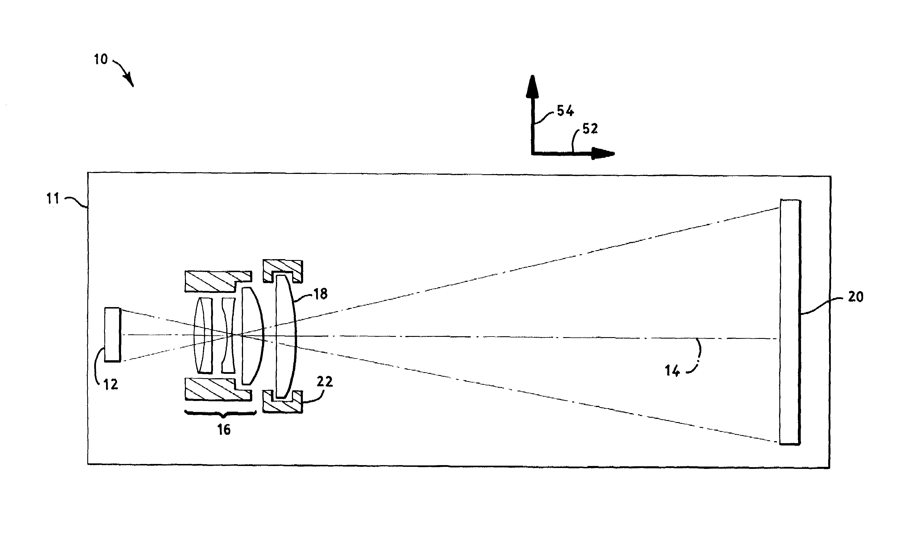
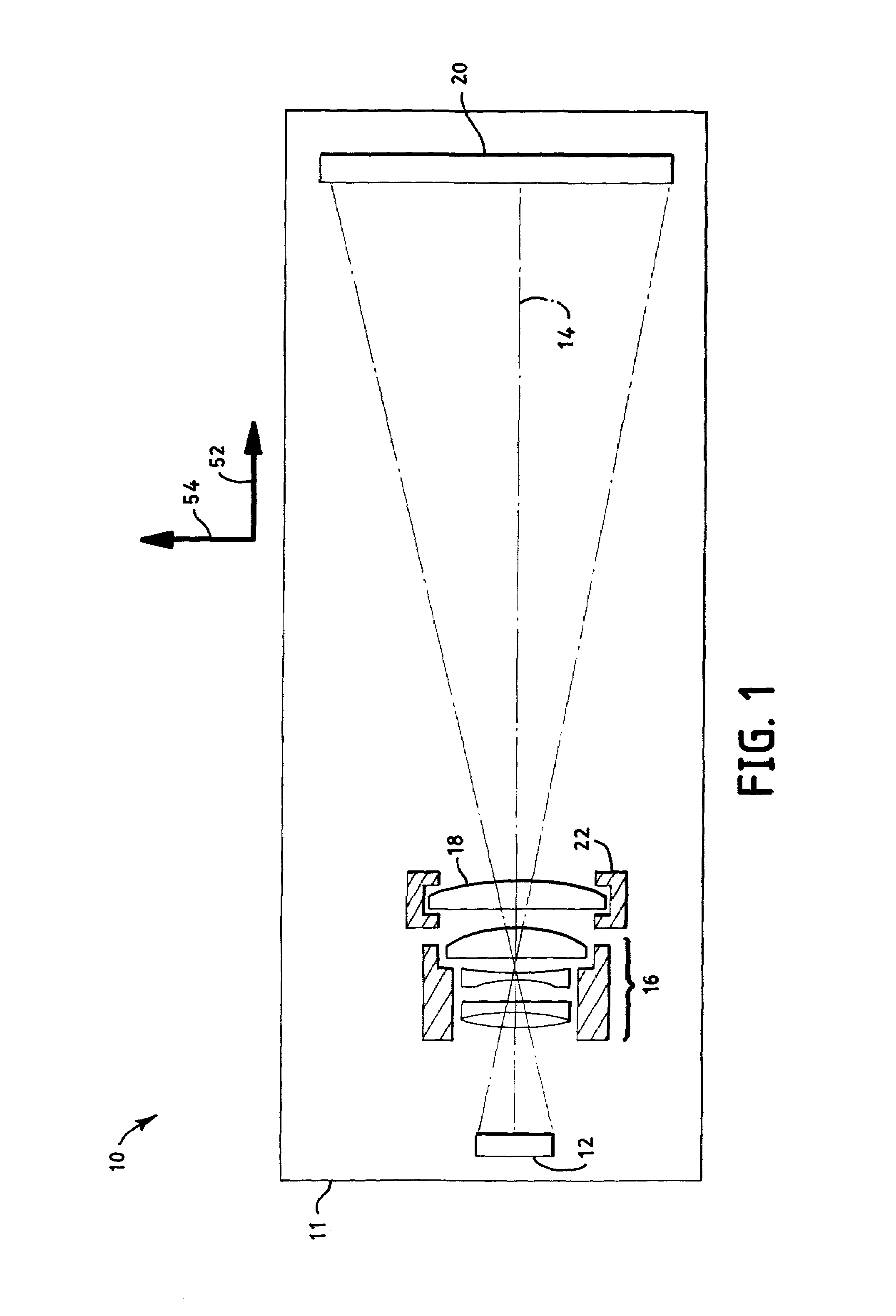
[0022]Referring to the FIG. 1, the digital printer 10 of the present invention is shown, in a first embodiment, to comprise a housing 11 that encloses, in a common cavity thereof, a digital area array display, or digital display 12, which may be located at one end of said housing 11. A first lens 16, and a transposable lens 18 are also located in the housing 11. The first lens 16 and transposable lens 18 being fixed along an optical axis 14 extending from said digital display 12, through a plurality of lenses, and ending on an image plane 20. The lenses are located between said digital display 12 and said image plane 20.

[0023]The digital display 20 may be a spatial light modulator, a liquid crystal display (LCD), an organic light emitting diode (OLED), a microdisplay, or other digital area array display known in the art. In a first embodiment, the digital display 12 is a microdisplay, which is a digital display under 1.5 inches diagonal that requires magnification or projection for ...

second embodiment

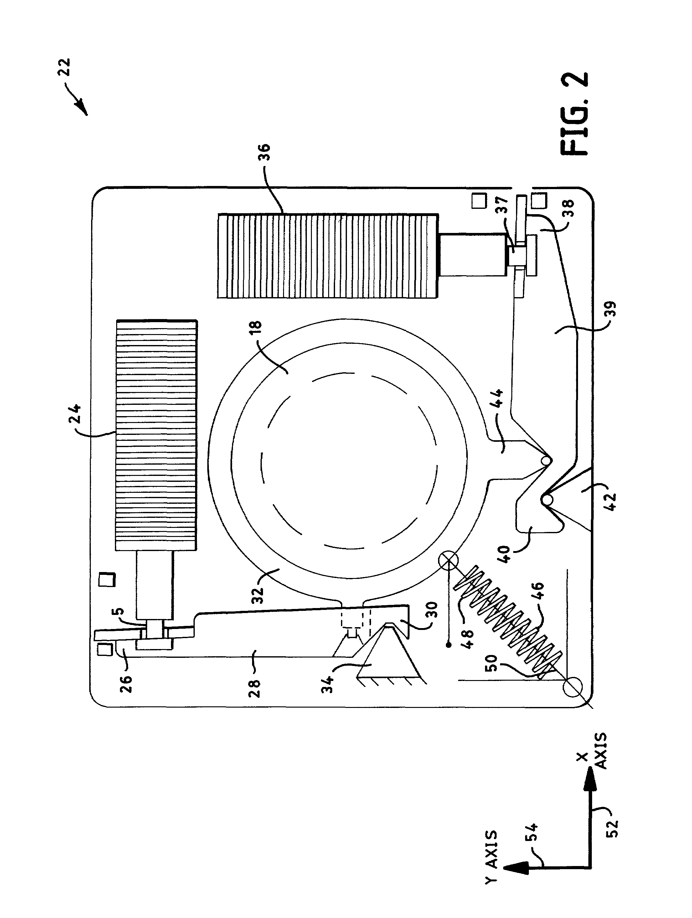
[0030]said device 22 also includes a second linear motion control device 36 being coupled at a second moving end 37, to a first end of second member 72. The second linear motion device 36 may be a solenoid or other similar device. The second member 70 also has a second end of second member 76 which pivots against a second support 78. The second end of second member 76 is also disposed with said second frame member 74. Said second frame member 74 is coupled with the transposable lens frame 32. Movement of the second linear motion control device 36 forces the second member 70 to pivot, and therefore, move the transposable lens frame 32 and transposable lens 18. The controlled movements of the two linear motion control devices accurately moves the transposable lens 18 in any combination of the positive or negative x-axis 52 or y-axis 54 directions.

[0031]FIG. 4 shows another view of a digital image printer 10 which incorporates the jogging system of the instant invention. As known in th...


PUM


Abstract

The present invention is an inexpensive and accurate means of improving resolution when imaging a small digital display onto a larger photosensitive medium. The device includes a printer having a housing that encloses, in a common cavity thereof, an arrangement comprising a digital area array display, a plurality of lenses, and an image plane. The digital area array display, the plurality of lenses, and the image plane are spaced along an optical axis extending from the digital area array display through the plurality of lenses, and toward the image plane such that a digital image provided by the display can be brought into focus onto the imaging plane by the plurality of lenses. One of the plurality of lenses is a transposable lens, the transposable lens capable of being transposed out of the optical axis during the operation of the printer, to increase the perceived resolution of the digital image focused onto the imaging plane. The invention provides in another aspect, a jogging mechanism for jogging a lens, the device comprising a first translating means for jogging an transposable lens in a first direction, a second translating means for jogging the transposable lens in a second direction, and a biasing means. In an alternate aspect, the present invention also provides a method of imaging a digital display onto an image plane, whereby the method of imaging increases the perceived resolution of the digital image focused onto said imaging plane.

Description

BACKGROUND[0001]1. The Field of the Invention[0002]In general, the present invention relates to digital image devices, and more particularly, to a novel means for improving resolution of an image projected from a digital display.[0003]2. Description of the Prior Art[0004]The internet is dramatically changing the way information is created and distributed. The increasing popularity of this world wide network has led to many new digital products used for a variety of purposes. For example, digital cameras capture images and store them as digital files which may be easily published on a website or instantly sent across the world.[0005]Digital files may also be viewed or imaged using various digital displays, such as microdisplays, spatial light modulators, liquid crystal displays (LCD), organic light emitting diode displays (OLED), or other known types of digital displays. Digital displays are comprised of arrays of pixels which illuminate at various discrete levels. Improving the reso...

Claims


Application Information

Patent Timeline
IPC IPC(8): G06K15/00B41J2/465
CPCB41J2/465
Inventor JOHNSON, BRUCE K.
Owner SENSHIN CAPITAL
Learn More