
System and method for determining formation fluid parameters using refractive index

a technology of refractive index and formation fluid, which is applied in the field of system and method for determining formation fluid parameters using refractive index, can solve the problems of high contamination of fluids that are withdrawn, the limited range of sensors used for measuring fluid resistivity in such tools, and the long construction period of expensive platforms with proper oil and gas handling facilities

Active Publication Date: 2006-02-14
BAKER HUGHES INC
View PDF12 Cites 41 Cited by
  • Summary
  • Abstract
  • Description
  • Claims
  • Application Information

AI Technical Summary

Benefits of technology

The present invention provides a method and system for determining parameters of interest of a formation fluid in a subterranean formation. This is achieved by using a tool attached to a tubular member in a borehole to determine the refractive index, pressure, and temperature of the formation fluid at a predetermined location. A reference fluid refractive index is calculated based on the formation fluid pressure and temperature. The parameter of interest is then determined by comparing the formation fluid refractive index to the reference fluid refractive index. This method and system provide a reliable and accurate way to determine important parameters of formation fluid composition in real-time, which can aid in the evaluation and production of oil and gas from subterranean formations.

Problems solved by technology

Oil and gas companies spend large sums of money in their attempts to find hydrocarbon deposits.
For deep offshore fields, before any hydrocarbons can be produced, it is first necessary to spend several years building very expensive platforms with proper oil and gas handling facilities.
Initially, fluids that are withdrawn may be highly contaminated by filtrates of the fluids (“muds”) that were used during drilling.
Sensors used for measuring the fluid resistivity in such tools are commonly limited in their useable sensor range.

Method used


Image

  • System and method for determining formation fluid parameters using refractive index
  • System and method for determining formation fluid parameters using refractive index
  • System and method for determining formation fluid parameters using refractive index

Examples


Embodiment Construction

[0021]The system and methods of the present invention overcome the foregoing disadvantages of the prior art by determining formation fluid density from refractive index measurements and relating the refractive index to desired formation fluid parameters of interest. The optical system of the present invention may be incorporated in wireline formation testers and in measurement while drilling formation testing systems. Examples of such systems are described in U.S. Pat. No. 5,377,755 A, U.S. Pat. No. 5,708,204 A, U.S. Pat. No. 5,803,186 A, U.S. Pat. No. 6,568,487 B2, U.S. Pat. No. 6,585,045 B2, each of which is incorporated herein by reference.

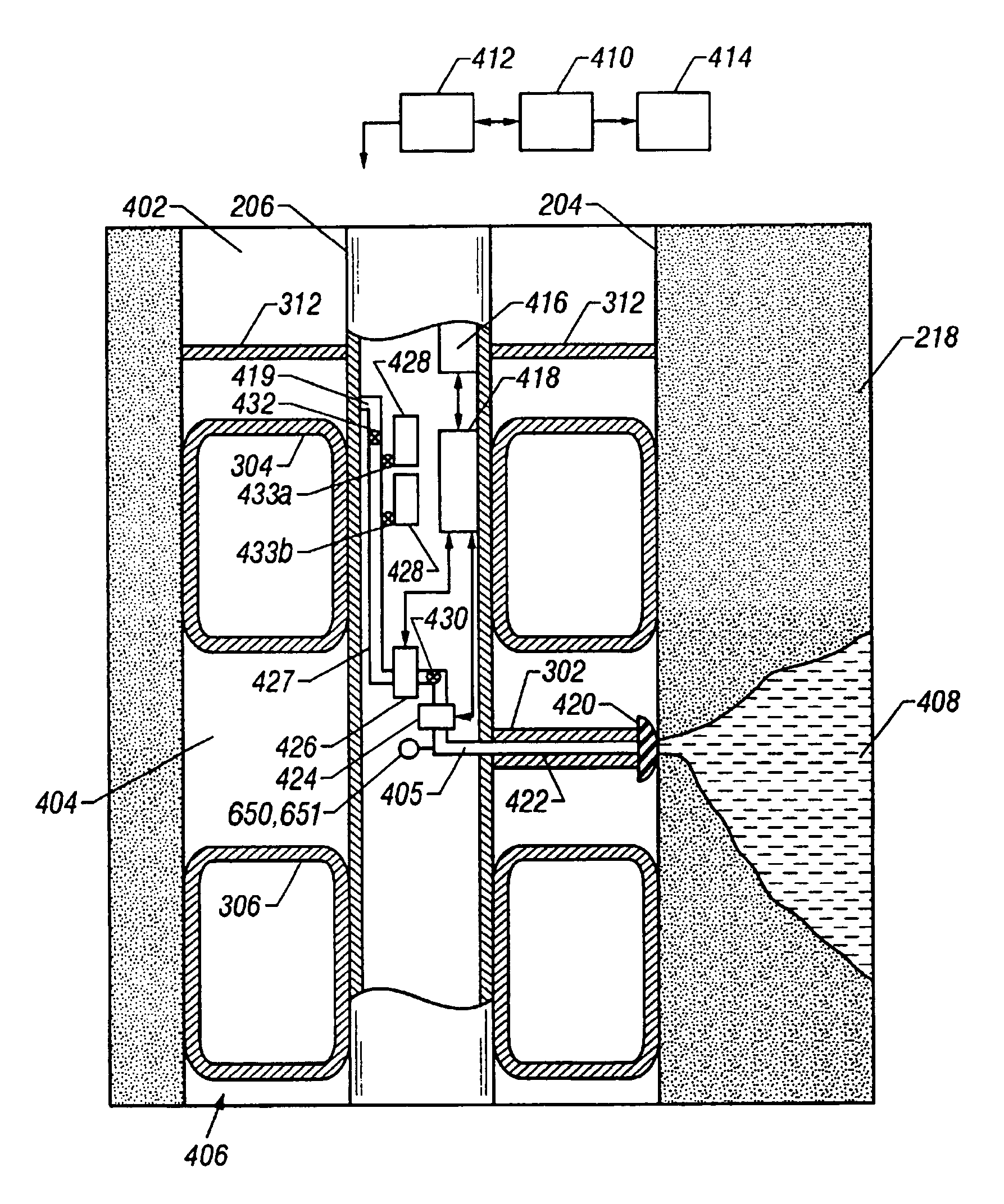
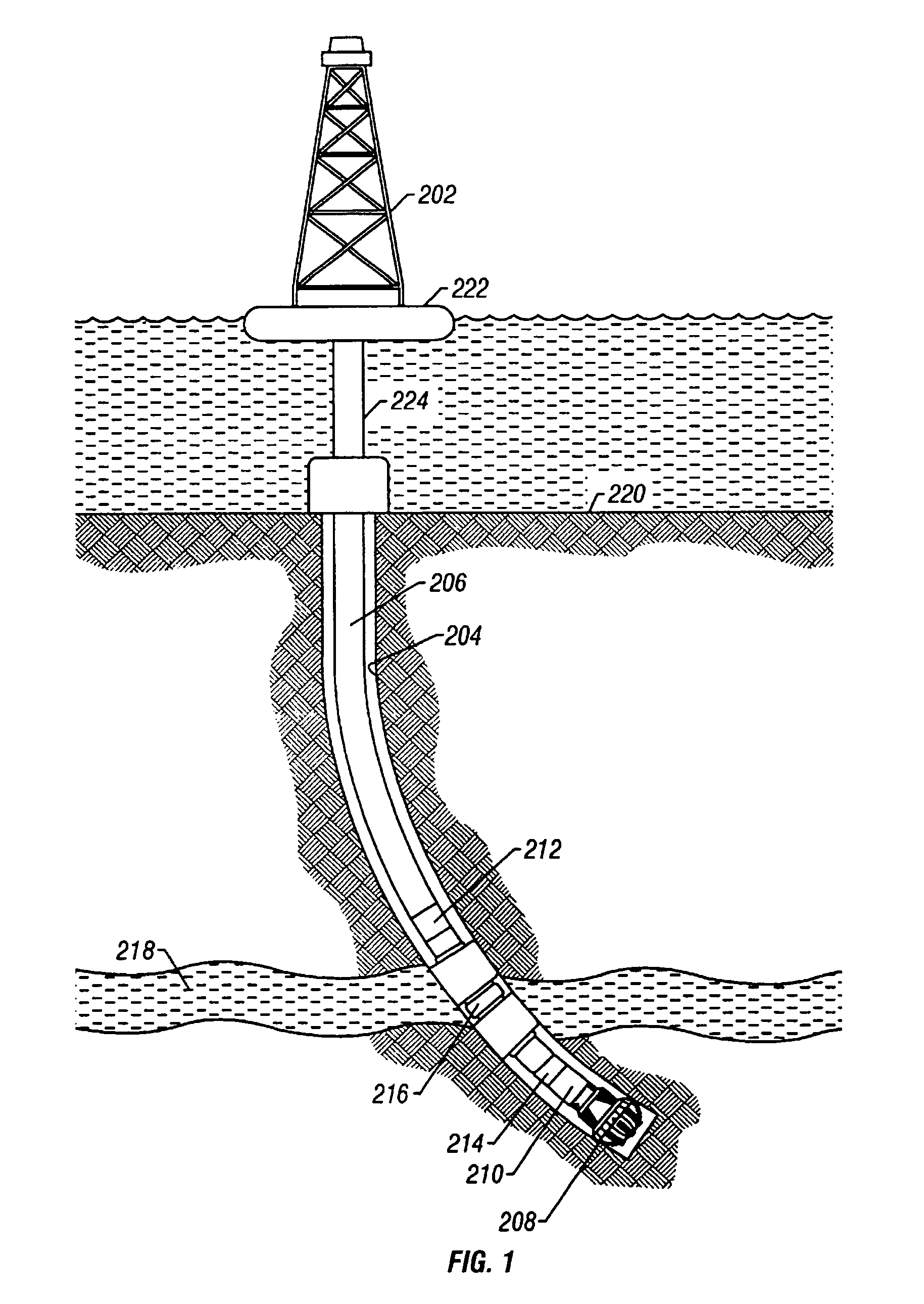
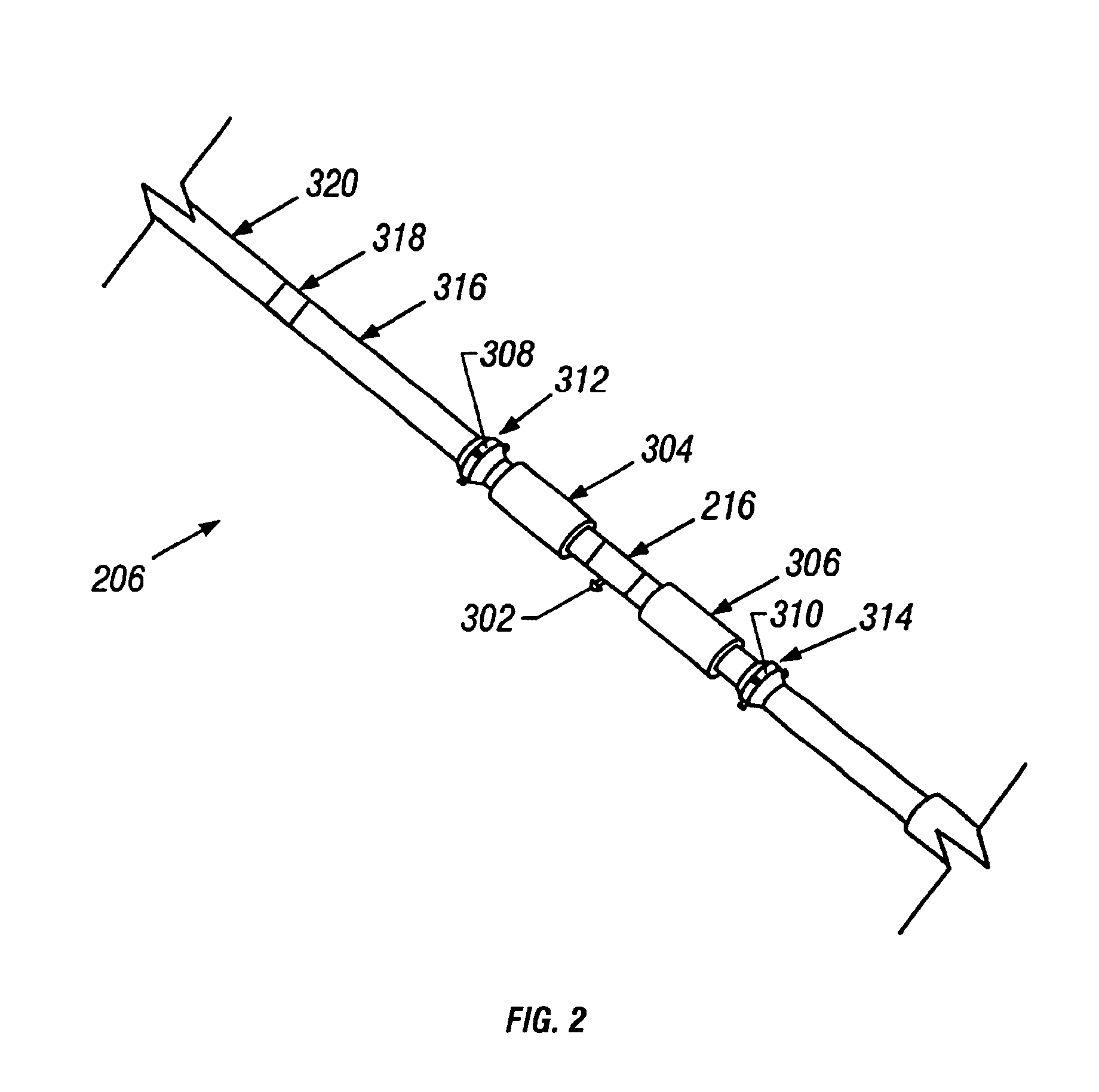
[0022]FIGS. 1–4 describe exemplary systems that may be used in the present invention. Any other suitable system for taking samples of formation fluid and making measurements thereon, such as those referenced above, may be used in the present invention. FIG. 1 is a drilling apparatus according to one embodiment of the present invention. A typica...


PUM


Abstract

A method and apparatus is described for determining a parameter of interest of a formation fluid. The method comprises moving a tool attached to a tubular member along a borehole in a subterranean formation. The tool is used to determine the refractive index, pressure and temperature of a formation fluid sample, in situ, at a predetermined location along the borehole. A refractive index of a reference fluid is calculated at the sample conditions. The parameter of interest of the formation fluid is determined at the predetermined location from a comparison of the corresponding formation fluid refractive index and the reference fluid refractive index at the predetermined location. In another embodiment, the refractive index of a natural gas sample is determined and compared to the refractive index of pure methane, at downhole conditions, to indicate the dryness of the natural gas.

Description

BACKGROUND OF THE INVENTION[0001]1. Field of the Invention[0002]This invention relates to the testing of underground formations or reservoirs. More particularly, this invention relates to an apparatus and a method for determining properties of formation fluids by detecting and interpreting the refractive index of the formation fluid.[0003]2. Description of the Related Art[0004]Oil and gas companies spend large sums of money in their attempts to find hydrocarbon deposits. They drill exploration wells in their most promising prospects and use these exploration wells not only to determine whether hydrocarbons are present but also to determine the properties of those hydrocarbons, which are present.[0005]For deep offshore fields, before any hydrocarbons can be produced, it is first necessary to spend several years building very expensive platforms with proper oil and gas handling facilities. The design specifications and cost of materials used in these facilities are strongly dependent ...

Claims


Application Information

Patent Timeline
Patent Type & Authority Patents(United States)
IPC IPC(8): E21B47/10G01V3/12G01V8/02
CPCG01V8/02
Inventor DIFOGGIO, ROCCO
Owner BAKER HUGHES INC
Learn More