
System and method for software component plug-in framework

a software component and plug-in framework technology, applied in the field of object component models, can solve the problems of increasing the risk of errors being introduced, compile problems also encountered, and tens of being very large applications in and of themselves, so as to reduce the amount of code copied/changed, promote the reuse of software code, and minimize redundant coding

Inactive Publication Date: 2006-02-07
ORACLE INT CORP
View PDF21 Cites 62 Cited by
  • Summary
  • Abstract
  • Description
  • Claims
  • Application Information

AI Technical Summary

Benefits of technology

[0013]Reduce the amount of code copied / changed across products through “componentization”, and encourage the reuse of software code to minimize redundant coding.

Problems solved by technology

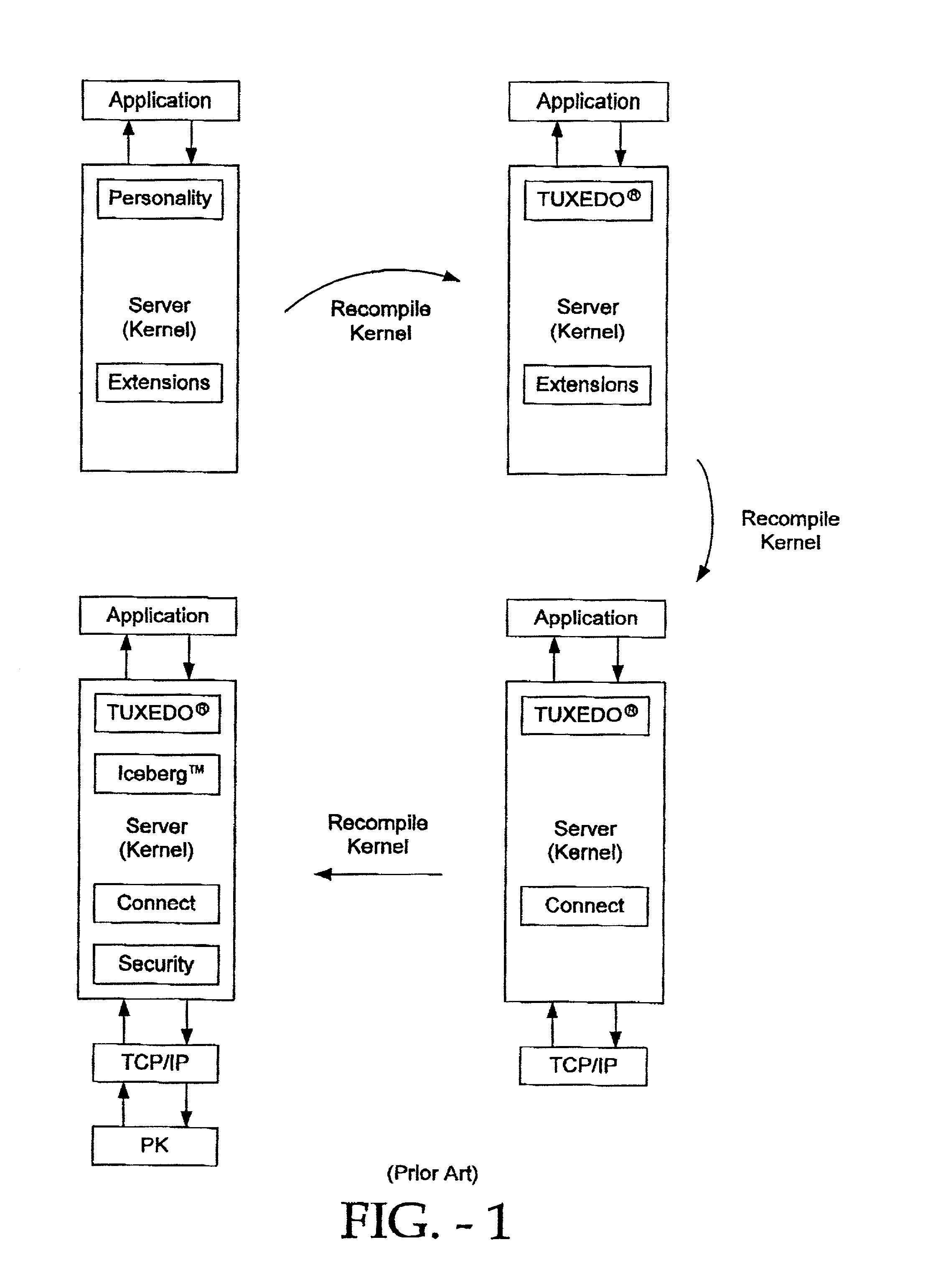
One of the primary disadvantage of such e-commerce or transaction servers is that they tend to be very large applications in and of themselves.
This necessitates server downtime and greatly increases the risks that errors will be introduced either during the recompile process or during the attempt to get the server running again in the shortest possible time.
Such compile problems are also encountered when adding routine server application updates and software patches.
The traditional server architecture likewise does not lend itself to reuse of Module code when the server kernel is itself replaced.
Much time and cost is spent re-writing code for new releases of a server product that does much the same as the last version of the code.
Customers who develop custom code to run with or within their server product find their code unusable with server releases of the server product.
The overall result is one of redundant coding, expense and wasted time.

Method used


Image

  • System and method for software component plug-in framework
  • System and method for software component plug-in framework
  • System and method for software component plug-in framework

Examples


example deployment

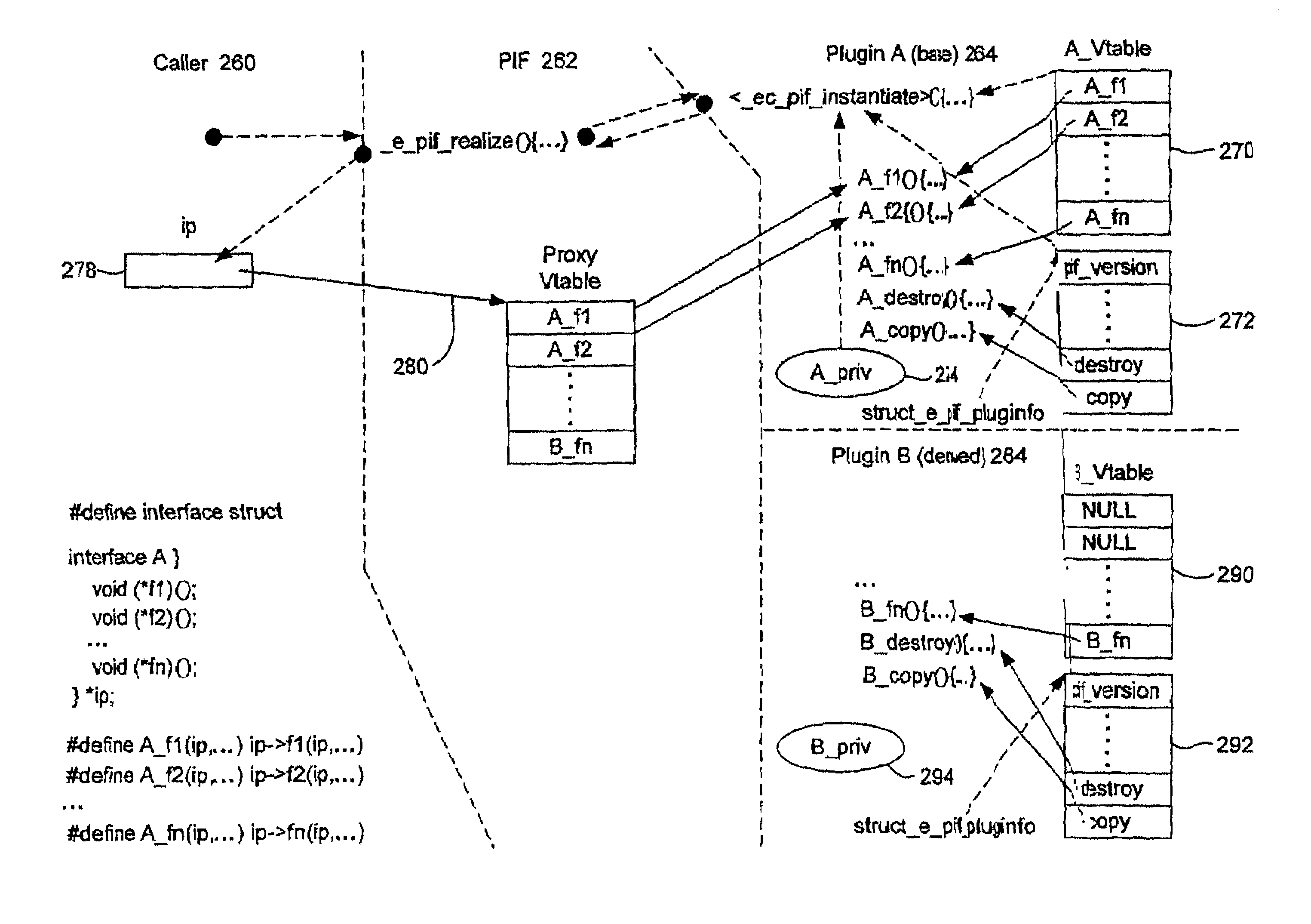
[0405]FIG. 13 illustrates a flowchart of an example of a method of deploying-the invention in a typical client / server environment. As shown in step 370 a set of services is specified by a developer or an administrator for each interface offered by the server. In step 372 implementations are developed for each interface to address the particular service needs of that interface. In step 374 different entities, such as other developers and third-party vendors develop different implementations for that interface, each implementation having a different feature set. In step 376 the calling application or client accesses the server engine and requests a particular implementation type. In step 378, the client makes a call to —e—pif—realize to realize the desired interface. In this process an interface unique identifier is generated and given to the client. The client may then choose (380, depending on its configuration) either a default implementation plugin for this implementation type, or...


PUM


Abstract

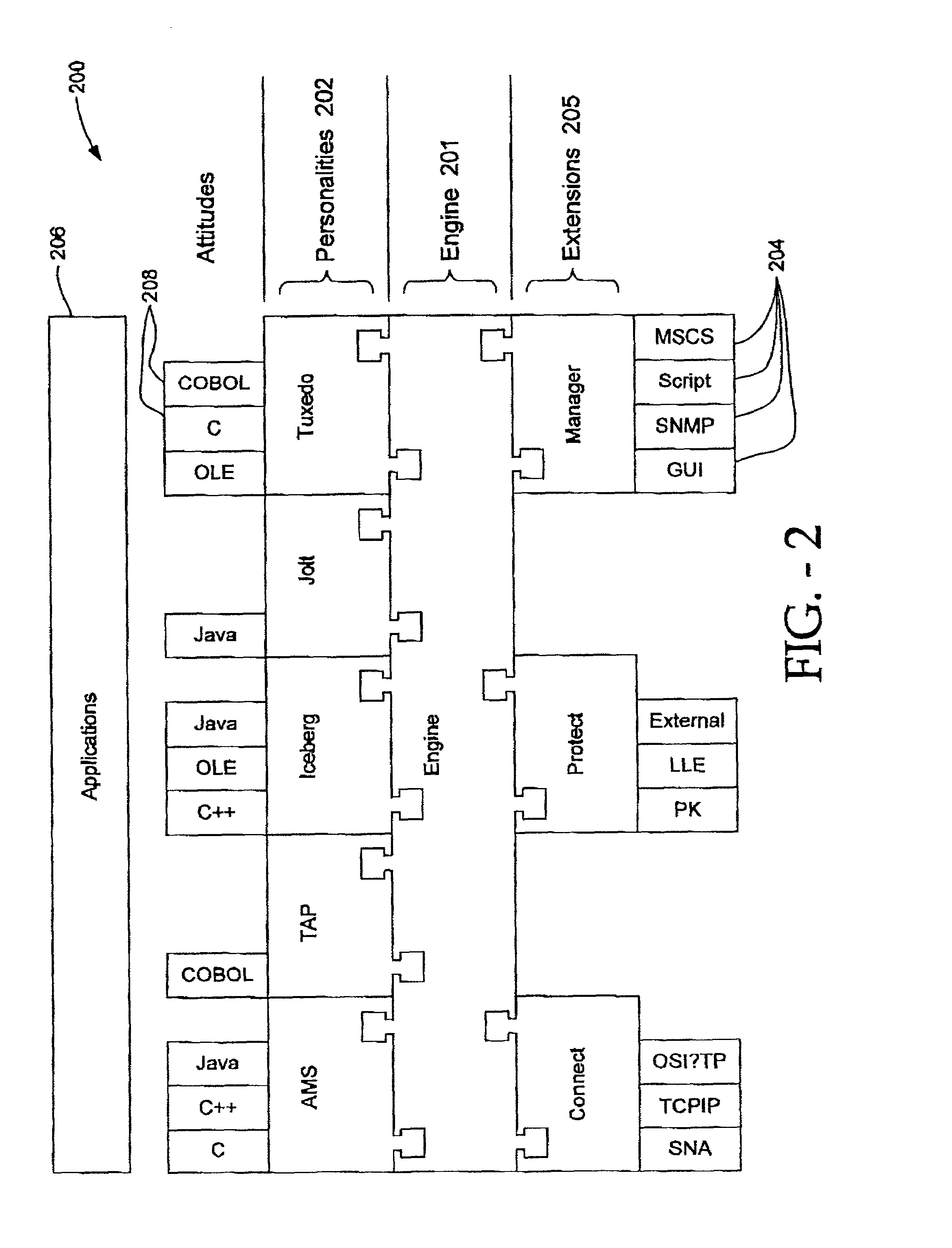
The invention provides a software component plugin framework. The system described supports dynamic loading, instantiation, and unloading of interface implementations (plugin modules), together with encapsulation of these interface implementations. The many benefits provided by the invention include software reuse, interoperability and fast product development cycles.

Description

[0001]This application claims priority from provisional application “SYSTEM AND METHOD FOR SOFTWARE COMPONENT PLUG-IN FRAMEWORK”, Application Ser. No. 60 / 294,467, filed May 30, 2001, and incorporated herein by reference.COPYRIGHT NOTICE[0002]A portion of the disclosure of this patent document contains material which is subject to copyright protection. The copyright owner has no objection to the facsimile reproduction by anyone of the patent document or the patent disclosure, as it appears in the Patent and Trademark Office patent file or records, but otherwise reserves all copyright rights whatsoever.FIELD OF THE INVENTION[0003]The invention relates generally to object component models and specifically to a system and a method for enabling plugin applications in a framework architecture.BACKGROUND OF THE INVENTION[0004]Today's business environment has become increasingly dependent on electronic commerce or “e-commerce” applications for their day to day operations. E-commerce applica...

Claims


Application Information

Patent Timeline
Patent Type & Authority Patents(United States)
IPC IPC(8): G06F9/46G06F9/54G06F9/44G06F9/445G06F13/00
CPCG06F9/54G06F9/44526
Inventor GUNDUC, MESUTANDRADE, JUANMICHAUD, JEFFPATRICK, PAUL
Owner ORACLE INT CORP
Learn More