
Multi-port system and method for routing a data element within an interconnection fabric

a multi-port system and data element technology, applied in the field of fabric interconnection system and method, can solve the problems of incompatibility with other technology, high cost of propriety system, latency and reliability, and other devices using, but not providing,

Inactive Publication Date: 2006-02-07
SAMSUNG ELECTRONICS CO LTD
View PDF11 Cites 46 Cited by
  • Summary
  • Abstract
  • Description
  • Claims
  • Application Information

AI Technical Summary

Benefits of technology

The solution provides a reliable, adaptable, and efficient data routing system that supports high-level protocols, enhances bi-directionality, and allows for longer distances between connections while maintaining low latency, thus addressing the limitations of existing interconnects.

Problems solved by technology

Other devices use, but do not provide, these functions.
Propriety systems are expensive, incompatible with other technology, and tend to populate the high end of the marketplace.
Electrical signaling characteristics, mechanical connections, and spatial locality are additional constraints, as are latency and reliability.
However, the routing devices and protocols that exist do not provide the advantages of spoof-proof bi-directionality.

Method used


Image

  • Multi-port system and method for routing a data element within an interconnection fabric
  • Multi-port system and method for routing a data element within an interconnection fabric
  • Multi-port system and method for routing a data element within an interconnection fabric

Examples


Embodiment Construction

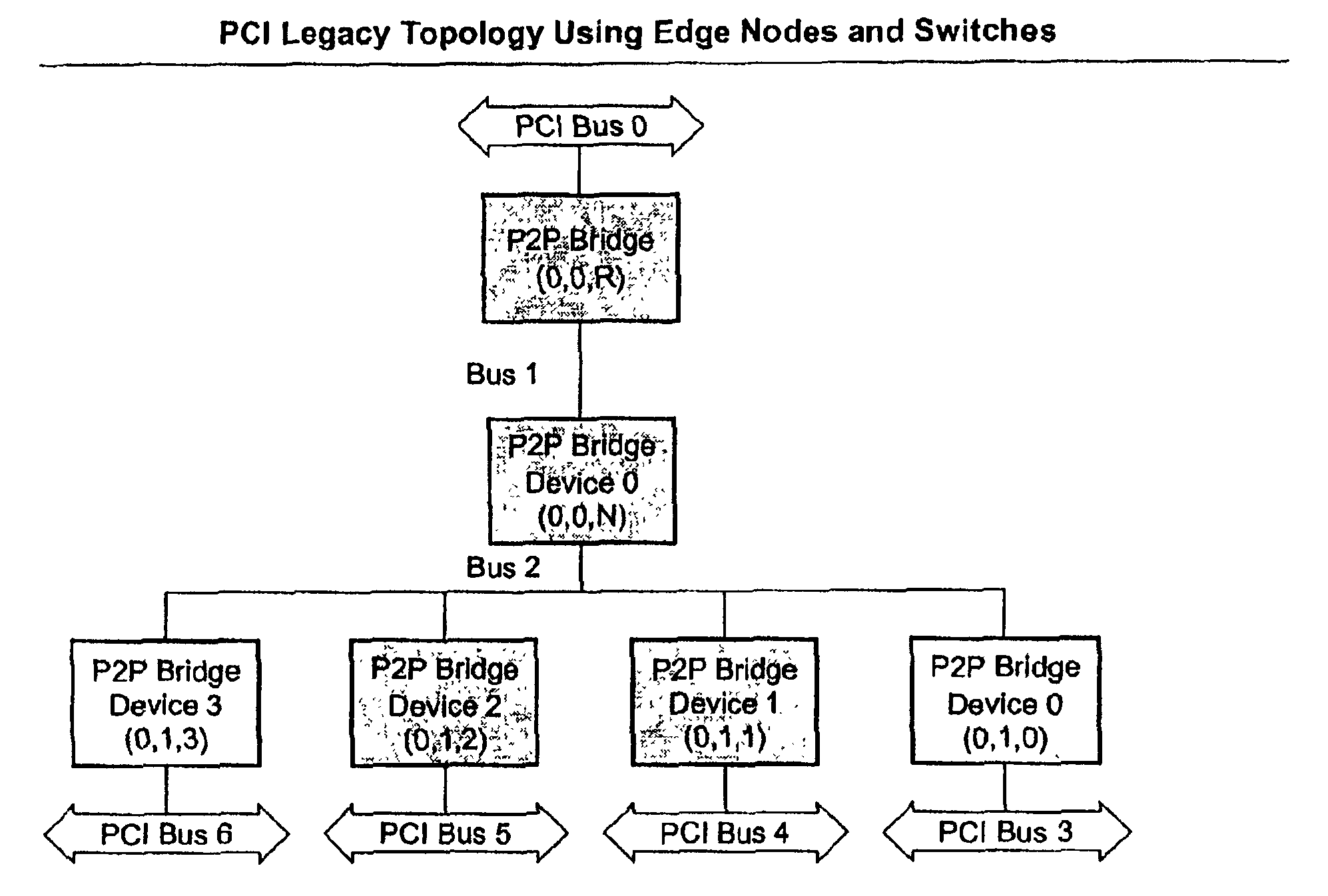
[0035]In the following detailed description of the embodiments, reference is made to the accompanying drawings that form a part hereof, and in which is shown by way of illustration specific embodiments in which the invention may be practiced. These embodiments are described in sufficient detail to enable those skilled in the art to practice the invention, and it is to be understood that other embodiments may be utilized and that structural, logical and electrical changes may be made without departing from the spirit and scope of the present inventions. The following detailed description is, therefore, not to be taken in a limiting sense. The leading digit(s) of the reference numbers in the Figures usually correspond to the figure number, with the exception that identical components which appear in multiple figures are identified by the same reference numbers.

Overview

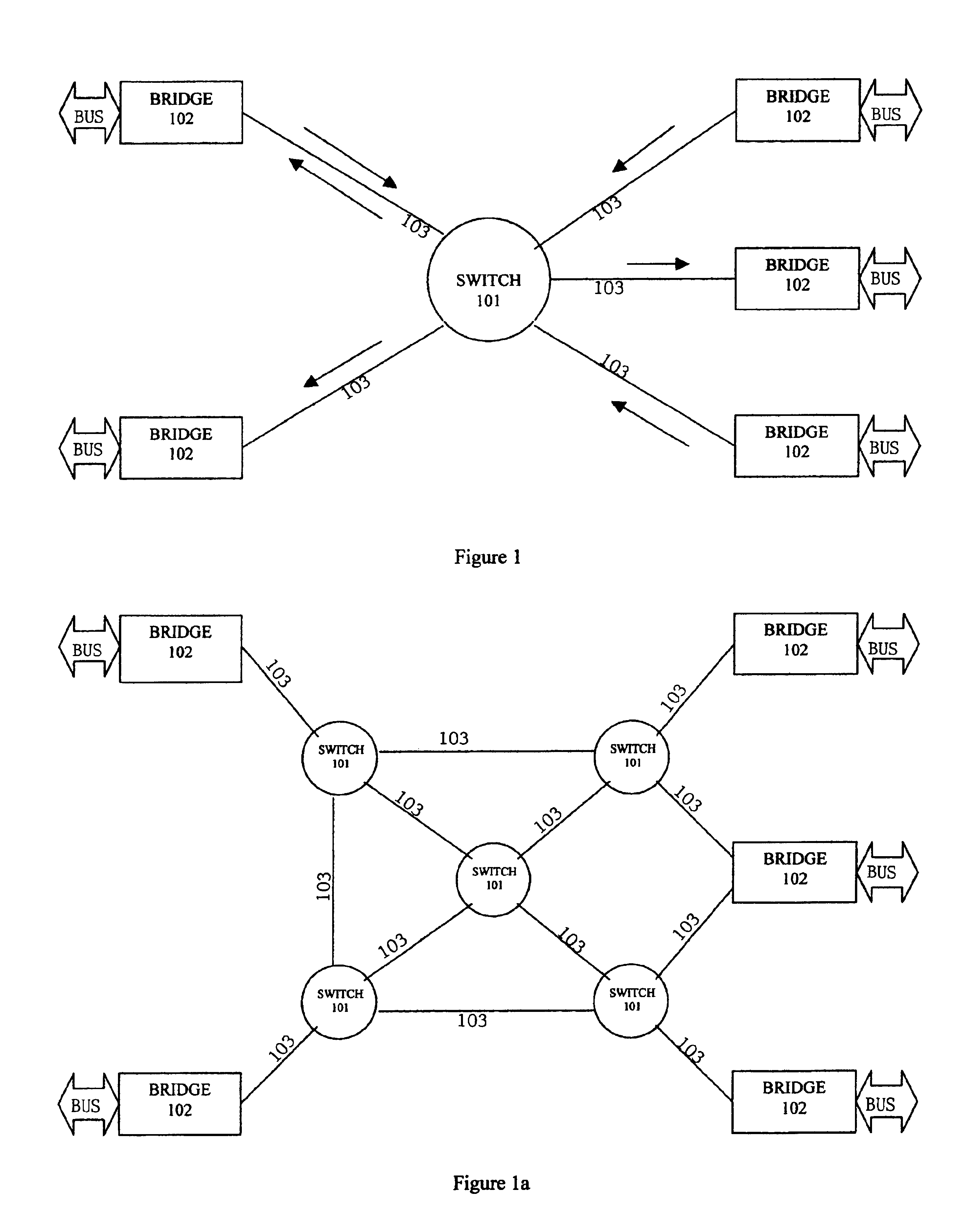
[0036]FIG. 1 and FIG. 1a are block diagrams depicting exemplary fabric topologies of a communication system interconne...


PUM


Abstract

The present invention relates generally to a generic fabric interconnect system and method for providing a data path between and among nodes and processing elements within an interconnection fabric. More specifically, there is provided a device accessible by a host processor for expanding access over a first bus to a second bus, the first bus and the second bus each being adapted to separately connect to respective ones of a plurality of bus-compatible devices, each device which comprise a link, a first circuit adapted to couple between the first bus and the link, and a second circuit adapted to couple between the link and the second bus, the first circuit and the second circuit each being operated as a bridge and being operable to (a) send outgoing information serially through said link in a form different from that of the first bus and the second bus (b) approve an initial exchange between the first bus and the second bus in response to pending bus transactions having a characteristic signifying a destination across a device, and (c) allow the host processor, communicating through the first bus, to individually address different selectable ones of the bus-compatible devices on the second bus: (i) using on the first bus substantially the same type of addressing as is used to access devices on the first bus, and (ii) without first employing a second, intervening one of the bus-compatible devices on the second bus.

Description

[0001]This application claims the benefit of and incorporates in its entirety herein by reference the contents of the following co-pending applications: application Ser. No. 60 / 330,215 filed Oct. 17, 2001, entitled “A Multi-Port System And Method For Routing A Data Element Within An Interconnection Fabric”BACKGROUND OF THE INVENTION[0002]1. Field of Invention[0003]The present invention relates generally to a fabric interconnect system and method for providing a data path between and among nodes and processing elements within an interconnection fabric.[0004]2. Brief Description of the Prior Art[0005]The components inside a computer communicate with each other in various ways. In general, most of the internal system components, including the processor, cache, memory, expansion cards and storage devices, exchange information over one or more “buses”.[0006]A bus refers to the physical medium, usually, a wire or a plurality of wires through which data is transmitted from one part of a co...

Claims


Application Information

Patent Timeline
Patent Type & Authority Patents(United States)
IPC IPC(8): G06F13/00G06F13/40H04L12/56
CPCG06F13/404G06F13/4027H04L49/25H04L49/252
Inventor BROCCO, LYNNE M.COMINS, TODD R.DOHM, NATHAN J.MAYHEW, DAVID E.MCMASTER, CAREY J.
Owner SAMSUNG ELECTRONICS CO LTD
Learn More