Energy saving electrical power control device and method

a technology of electrical power control device and energy saving electrical controller, which is applied in the direction of electric variable regulation, process and machine control, instruments, etc., can solve the problems of load generating momentary voltage surge and transient voltage not being able to be generated during transition, so as to reduce the power factor and reduce the power consumption of inductive-dissipative

Inactive Publication Date: 2006-02-07
SINETEK INC
View PDF8 Cites 13 Cited by
  • Summary
  • Abstract
  • Description
  • Claims
  • Application Information

AI Technical Summary

Benefits of technology

[0013]The present invention provides an electrical load controller that reduces the power consumption of inductive-dissipative or inductive-resistive loads, including for example fluorescent lighting, and including purely resistive loads to which an inductor has been coupled, without any substantial reduction in the power factor. The method and device of the invention interrupts the AC power supply to the load during a plurality of intervals within each half cycle of the AC mains power frequency. In the case of inductive-dissipative or inductive-resistive loads, each interruption of the AC supply power will cause the load to generate a momentary voltage surge unless a path is created for the current, which is accordingly circulated to the load during the interrupt interval.
[0018]At the same time switching the power switch “on” and having the appropriate circulating switch element “on” outside the crossover lag zone allows for seamless transitions, which are completely latency-independent, to the “off” state when the power switch is shut off, which thus considerably simplifies the timing circuitry for the switch drivers.
[0020]As long as the starting and ending points for the concurrent “on” conditions of the power supply and appropriate element of the current circulating switches are both selected to be within positions of the voltage and current waveforms where the voltage and current levels are sufficiently low that cross-conduction currents and transient surge voltages are not substantial enough to affect the switching circuit components, the invention will operate as described to reduce power consumption by the load.

Problems solved by technology

In the case of inductive-dissipative or inductive-resistive loads, each interruption of the AC supply power will cause the load to generate a momentary voltage surge unless a path is created for the current, which is accordingly circulated to the load during the interrupt interval.
Additionally, transient voltages cannot be generated during transition from “on” to “off” of the power switch as the circulating current switch is already available to allow circulating current flow.

Method used


Image

  • Energy saving electrical power control device and method
  • Energy saving electrical power control device and method
  • Energy saving electrical power control device and method

Examples


Embodiment Construction

[0033]A preferred embodiment of the invention will be described in the context of a power control device for controlling the electrical power supplied to ballasted fluorescent lights, which behave like an inductive-dissipative load in an electric circuit. It will be appreciated that the invention can be applied equally to other inductive and inductor-like loads, including electric motors, compressors, variable speed drives and the like. The invention can also be used with resistive loads, however the invention is most advantageously used with inductive and inductor-like loads.

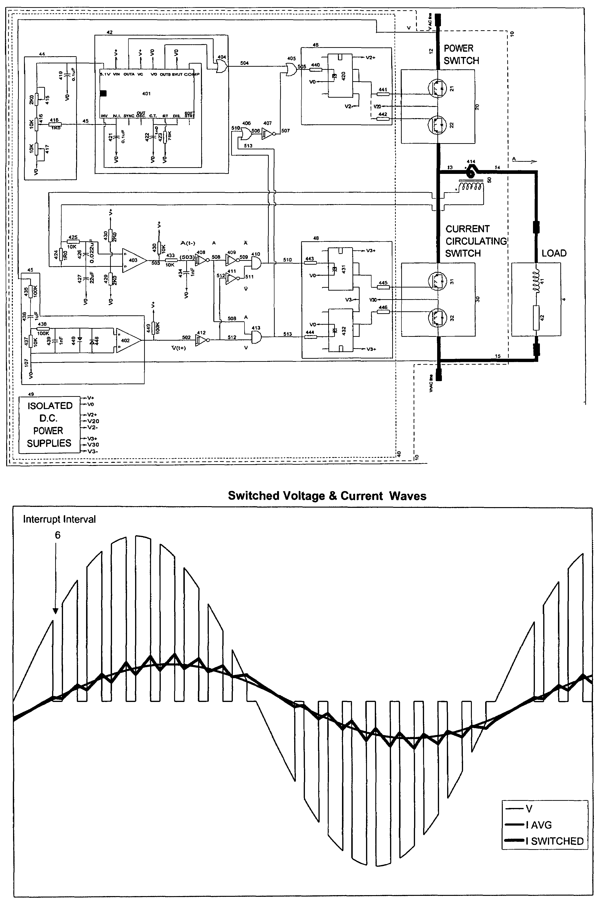
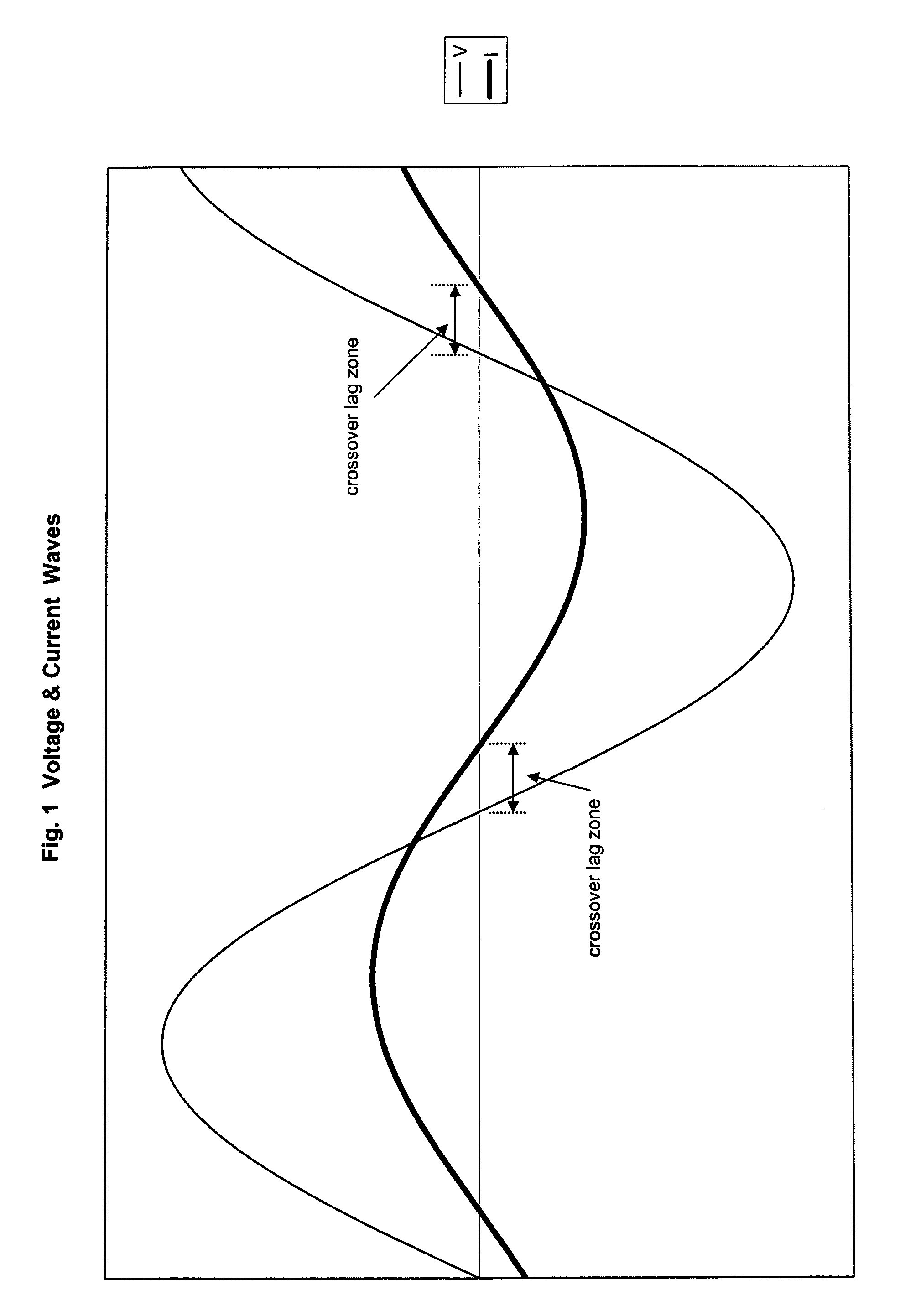
[0034]FIG. 1 illustrates the voltage waveform of a typical 60 Hz alternating current mains power supply. Within each cycle is a positive half cycle and a negative half cycle, respectively defined between sequential zero crossing points. According to the invention, the AC mains power supply is interrupted during a plurality of intervals 6 within each half cycle.

[0035]One example of a modified power supply produc...


PUM


Abstract

An electrical load power control device is described that reduces the power consumption of inductive and inductive-dissipative loads, including for example fluorescent lighting. The power circuit of the invention interrupts AC power supply to the load during a plurality of intervals within each half cycle of the AC mains signal frequency whilst providing an alternate path for current flow during the interruption to maintain a sinusoidal-like current to the load. During a crossover lag zone encompassing zero crossing points of the voltage and current and during which the voltage and current have opposite polarities, both elements of the power switch are switched to the “on” condition, one element of the circulating switch is switched to the “on” condition when a positive current is flowing in the load and the other element of the circulating switch is switched to the “on” condition when a negative current is flowing in the load. The power factor presented by the load and other current parameters of the load such as form factor and total harmonic distortion may be desirably modified. In the preferred embodiment an oscillator has a duty cycle control circuit which deactivates the power switch during a predetermined portion of the oscillator duty cycle. The duty cycle establishes the amount of power reduction.

Description

FIELD OF THE INVENTION[0001]This invention relates to energy saving electrical controllers. In particular, this invention relates to an energy saving power control device and method which reduces the power consumption of inductive-dissipative and inductive-resistive loads.BACKGROUND OF THE INVENTION[0002]Conservation and the intelligent use of energy resources are extremely important in today's society. In the case of electricity in particular, demands are constantly increasing and in many regions resources are strained. There have accordingly been many devices developed over the years to reduce electrical power consumption by electrical loads.[0003]When used with inductive-dissipative loads such as ballasted gas discharge lamps or electric motors, the removal of a portion of each half cycle of the AC fundamental power can result in a significant decrease in the power factor. The power factor is the ratio of true power to apparent power, which can be expressed as: power⁢⁢factor=∑0n⁢...

Claims


Application Information

Patent Timeline
Patent Type & Authority Patents(United States)
IPC IPC(8): H01H31/34H02M5/293
CPCH02M5/293
Inventor GIBSON, J. ALAN
Owner SINETEK INC
Why Eureka
Try Eureka