
EGR-gas temperature estimation apparatus for internal combustion engine

a technology of egr gas and temperature estimation apparatus, which is applied in the direction of machines/engines, electric control, instruments, etc., can solve the problem that the temperature of egr gas at the outlet of the egr gas cooling apparatus cannot be accurately estimated, and achieve the effect of accurate estimation

Inactive Publication Date: 2006-02-07
TOYOTA JIDOSHA KK
View PDF14 Cites 34 Cited by
  • Summary
  • Abstract
  • Description
  • Claims
  • Application Information

AI Technical Summary

Benefits of technology

[0011]In view of the foregoing, an object of the present invention is to provide an EGR-gas temperature estimation apparatus for an internal combustion engine, which apparatus can accurately estimate an EGR-gas temperature on the outlet side of an EGR-gas cooling apparatus, by determining the cooling efficiency of the EGR-gas cooling apparatus on the basis of an EGR-gas temperature on the inlet side of the EGR-gas cooling apparatus.
[0012]Another object of the present invention is to provide an EGR-gas temperature estimation apparatus for an internal combustion engine, which apparatus can accurately estimate EGR-gas temperature at an EGR-gas outlet, which is a connection portion between an exhaust circulation pipe and an intake passage, by determining the cooling efficiency of an EGR-gas cooling apparatus on the basis of EGR-gas temperature at the inlet of the exhaust circulation pipe.
[0014]As described above, in the present apparatus, since the cooling efficiency of the EGR-gas cooling apparatus is determined on the basis of the EGR-gas temperature on the inlet side of the EGR-gas cooling apparatus as well, the determined cooling efficiency is close to the actual value. Therefore, the present apparatus can accurately estimate the temperature of the EGR gas on the outlet side of the EGR-gas cooling apparatus.
[0019]As described above, in the present apparatus, since the cooling efficiency of the EGR-gas cooling apparatus is determined on the basis of the exhaust-circulation-pipe-inlet EGR-gas temperature as well, the determined cooling efficiency is close to the actual value. Therefore, the present apparatus can accurately estimate the exhaust-circulation-pipe-outlet EGR-gas temperature.
[0021]The temperature of the coolant of the EGR-gas cooling apparatus causes changes in the exhaust-circulation-pipe-outlet EGR-gas temperature. By means of the above-described configuration, the temperature of the coolant of the EGR-gas cooling apparatus is taken into consideration to estimate the exhaust-circulation-pipe-outlet EGR-gas temperature, the exhaust-circulation-pipe-outlet EGR-gas temperature can be estimated more accurately.
[0023]This configuration enables the phenomenon such that “the temperature of EGR-gas decreases greatly as the difference (ΔT=Tex−Treibai) between the exhaust-circulation-pipe-inlet EGR-gas temperature Tex and the obtained coolant temperature Treibai increases” is properly reflected in estimation of the exhaust-circulation-pipe-outlet EGR-gas temperature Tegr. Therefore, the exhaust-circulation-pipe-outlet EGR-gas temperature can be estimated more accurately.

Problems solved by technology

Accordingly, the above-described conventional technique that estimates the cooling efficiency of the EGR-gas cooling apparatus without consideration of the temperature of the EGR gas flowing into the EGR-gas cooling apparatus has a problem in that the temperature of the EGR gas at the outlet of the EGR-gas cooling apparatus cannot be accurately estimated.

Method used


Image

  • EGR-gas temperature estimation apparatus for internal combustion engine
  • EGR-gas temperature estimation apparatus for internal combustion engine
  • EGR-gas temperature estimation apparatus for internal combustion engine

Examples


Embodiment Construction

[0044]An embodiment of an control apparatus of an internal combustion engine (diesel engine) which incorporates an EGR-gas temperature estimation apparatus according to the present invention, as well as an EGR control apparatus, will now be described with reference to the drawings.

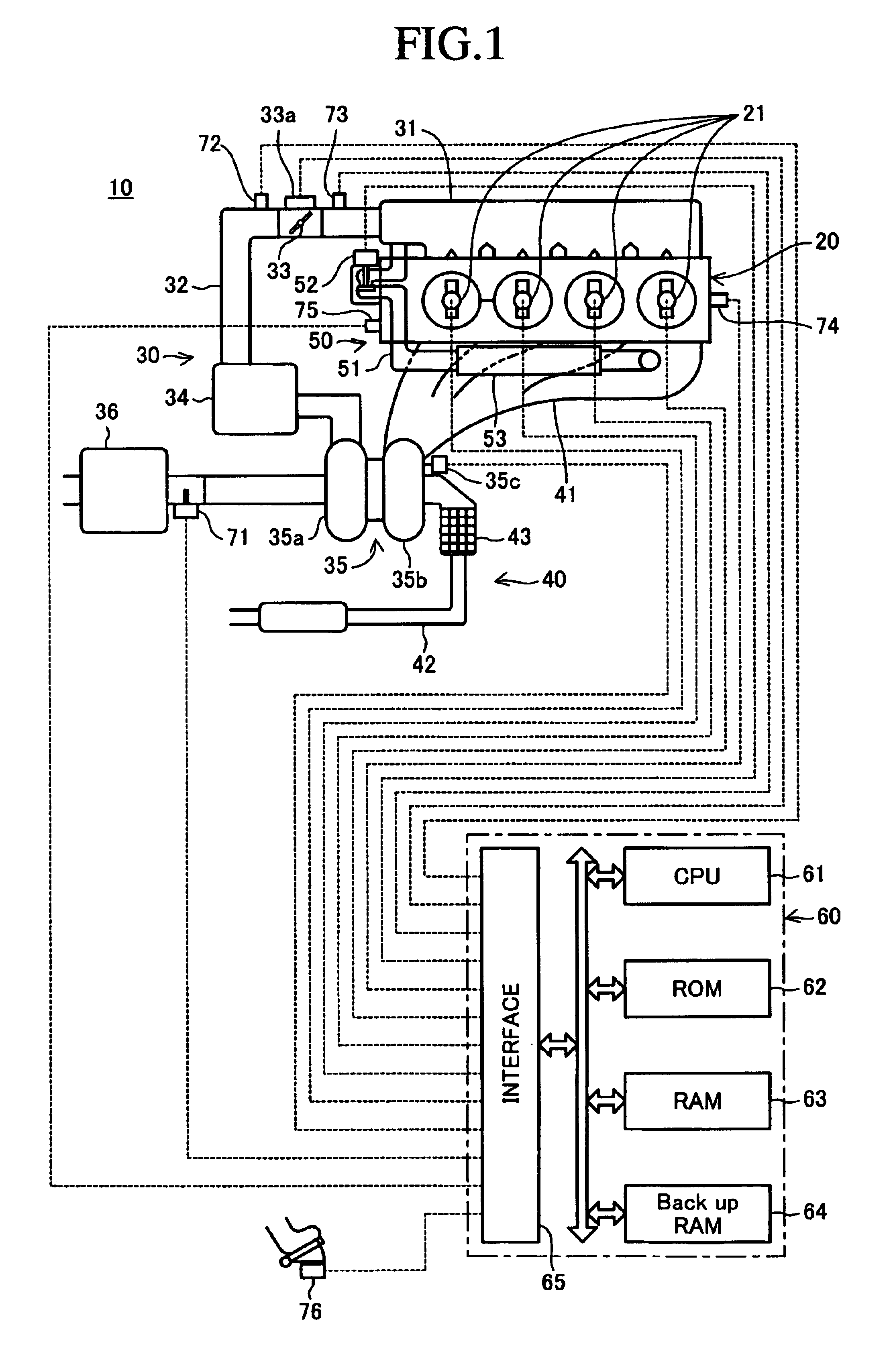
[0045]FIG. 1 schematically shows the entire configuration of a system in which the engine control apparatus according to the present invention is applied to a four-cylinder internal combustion engine (diesel engine) 10. This system comprises an engine main body 20 including a fuel supply system; an intake system 30 for introducing gas to combustion chambers of individual cylinders of the engine main body 20; an exhaust system 40 for discharging exhaust gas from the engine main body 20; an EGR apparatus 50 for performing exhaust circulation; and an electric control apparatus 60.

[0046]Fuel injection valves 21 are disposed above the individual cylinders of the engine main body 20. The fuel injection valves 21...


PUM


Abstract

An EGR-gas temperature estimation apparatus for an internal combustion engine which has an exhaust circulation pipe and an EGR-gas cooling apparatus. The estimation apparatus obtains the cooling efficiency ηegr of the EGR-gas cooling apparatus from the temperature Tex of EGR gas at the inlet of the exhaust circulation pipe and the flow rate Gegr of the EGR gas, and obtains the temperature THW of engine cooling water, used as a coolant for the EGR-gas cooling apparatus. Subsequently, the estimation apparatus calculates the temperature Tegr of the EGR gas at the outlet of the exhaust circulation pipe by the expression Tegr=Tex−ηegr·(Tex−THW). Since the cooling efficiency ηegr greatly changes depending on the EGR-gas flow rate Gegr and the EGR-gas temperature Tex, the estimation apparatus can accurately estimate the cooling efficiency ηegr, and therefore can accurately estimate the EGR-gas temperature Tegr.

Description

BACKGROUND OF THE INVENTION[0001]1. Field of the Invention[0002]The present invention relates to an EGR-gas temperature estimation apparatus, for an internal combustion engine, which estimates the temperature of EGR gas flowing through an exhaust circulation pipe of the internal combustion engine.[0003]2. Description of the Related Art[0004]Conventionally, there has been widely known an EGR apparatus which circulates a portion of exhaust gas of an internal combustion engine to an intake passage via an exhaust circulation pipe, in order to reduce the amount of nitrogen oxides (NOx) discharged from the engine. Such an EGR apparatus is applied to both spark-ignition engines and diesel engines.[0005]Meanwhile, in a diesel engine, combustion is effected at a super-lean air-fuel ratio. Specifically, since oxygen required for combustion is sufficiently present, the output of the diesel engine greatly depends on fuel quantity. Therefore, in a diesel engine, when the quantity of exhaust gas ...

Claims


Application Information

Patent Timeline
IPC IPC(8): F02B33/44F02M25/07F02D21/08F02D41/00F02D41/40F02D45/00
CPCF02D41/0072F02D41/145F02M25/0726F02M25/0731F02D41/401F02D2041/0067Y02T10/47F02M25/0707F02M25/0738F02D2041/007F02M26/05F02M26/22F02M26/28F02M26/33Y02T10/40
Inventor MATSUNAGA, AKIOKATSUNO, MASATO
Owner TOYOTA JIDOSHA KK
Learn More