
Method and apparatus for providing adaptive illumination

Inactive Publication Date: 2006-01-31
MICROSOFT INT HLDG BV
View PDF76 Cites 70 Cited by
  • Summary
  • Abstract
  • Description
  • Claims
  • Application Information

AI Technical Summary

Benefits of technology

[0021]In some embodiments of the present invention, the controller of the illumination system is programmable to provide different desired lighting effects and / or to identify different types of objects and features of a scene that is illuminated by the illumination system.
[0068]In some embodiments of the present invention, the automotive light is a headlight. Optionally, the controller process images provided by the photosurface to identify oncoming vehicles and when an oncoming vehicle is identified, the controller controls the light providing regions to prevent blinding the driver of the oncoming vehicle.

Problems solved by technology

As a result, achieving effective illumination of a scene is often a relatively complicated, subtle and arduous task.

Method used


Image

  • Method and apparatus for providing adaptive illumination
  • Method and apparatus for providing adaptive illumination
  • Method and apparatus for providing adaptive illumination

Examples


Embodiment Construction

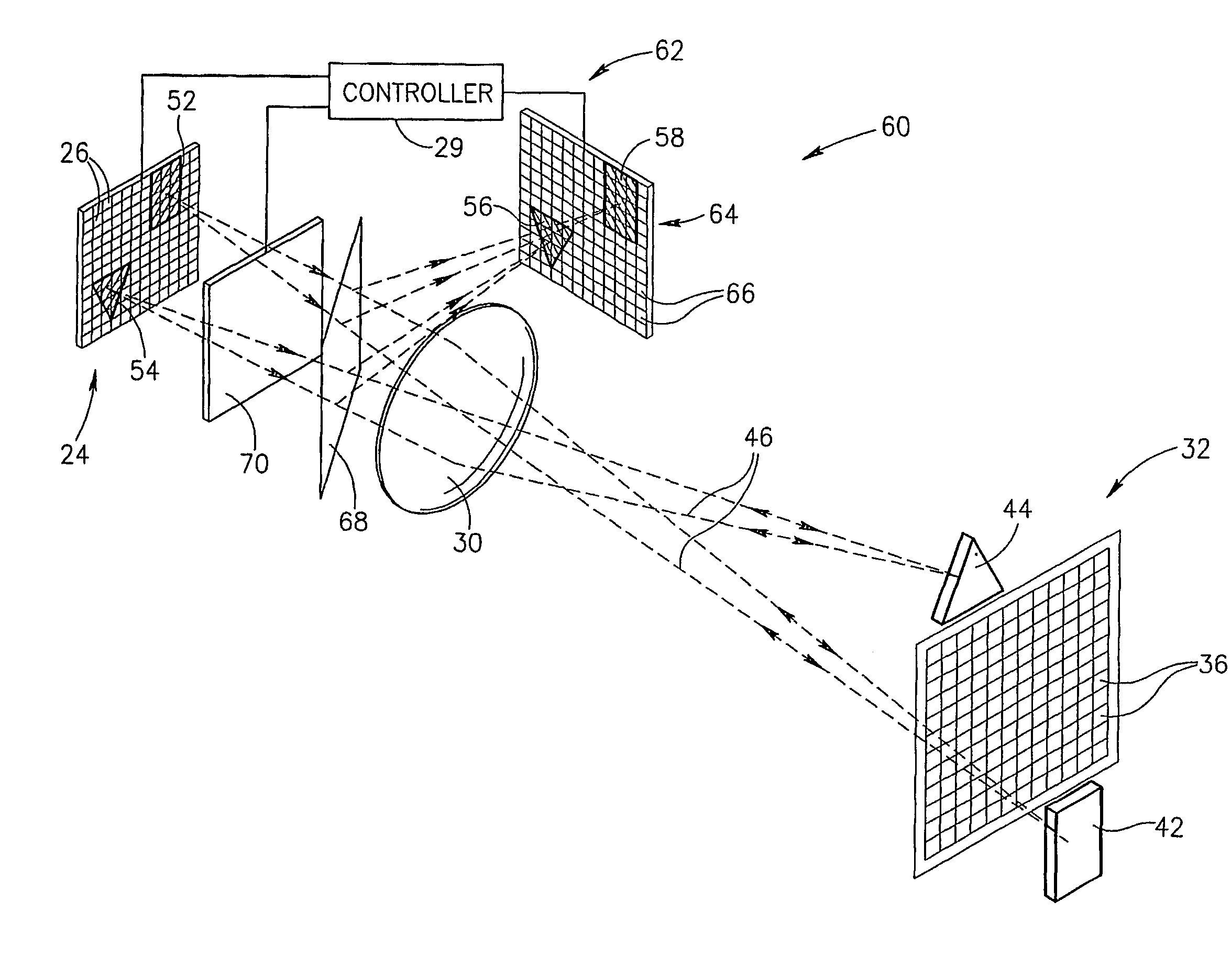
[0083]FIG. 1 schematically shows an illumination system 20, in accordance with an embodiment of the present invention, comprising a range finder 22, an illuminator 24 having luxels, schematically represented by rectangular regions 26 of the illuminator, and a controller 28.

[0084]Luxels 26 may provide and control light by emission, reflection or transmission, or a combination of these processes. For example, luxels 26 may comprise one or a combination of light sources, such as for example semiconductor lasers, that provide light by emission, micromirrors that provide light by reflection and / or liquid crystal cells that provide light by transmission.

[0085]In some embodiments of the present invention, luxels 26 are “color” luxels, for which spectrum and intensity of light provided by the luxels can be controlled to provide different color light. For example, in some embodiments of the present invention, luxels 26 are “RGB” luxels controllable to provide different combinations of R, G a...


PUM


Abstract

An illumination system (20, 72, 110, 142) for illuminating a scene comprising: an illuminator (24, 74, 116) having a plurality of substantially contiguous independently controllable light (26, 76) providing regions each of which provides light that illuminates a different region of the scene; optics (30) that directs light from the illuminator to the scene; a range finder (22, 64, 112) that determines distances to regions of the scene; and a controller (28, 29, 118) that controls the plurality of light providing regions to provide light for illuminating the scene responsive to distances determined by the range finder (22, 64, 112).

Description

RELATED APPLICATIONS[0001]The present application is a US National Application of PCT / IL01 / 00627, filed on Jul. 9, 2001. This application is also a continuation-in-part of PCT Application No. PCT / IL00 / 00404, filed on Jul. 9, 2000, which is a continuation-in-part of U.S. Application No. 09 / 250,322, filed on Feb. 16, 1999, now U.S. Pat. No. 6,445,884.FIELD OF THE INVENTION[0002]The present invention relates to adapting illumination of a scene responsive to features and characteristics of the scene and in particular to automatically adapting the illumination to characteristics and features of the scene.BACKGROUND OF THE INVENTION[0003]A visual impression of a scene and objects and features in the scene is generally a function of illumination of the scene. Objects in a scene that are illuminated so that they contrast strongly with their local background tend to capture our attention. Acuity with which the eye is able to distinguish details of features in a scene and impressions of featu...

Claims


Application Information

Patent Timeline
IPC IPC(8): G03B15/03B60Q1/08F21V1/00B60Q1/52G01C11/02G01S7/48G01S7/481G01S7/51G01S15/89G01S17/08G01S17/18G01S17/88G01S17/89G02B7/32G02B27/00G03B1/00H04N5/225H04N5/235
CPCB60Q9/008F21S48/115F21S48/1747G01C11/025H04N5/2354G01S17/08G01S17/89G02B7/32H04N5/2256B60Q2400/50G01S7/4812G01S17/107G01S17/88G01S7/51F21S41/141F21S41/147F21S41/663G01S17/18H04N23/56H04N23/74
Inventor BRAUN, ORI J.YAHAV, GIORA
Owner MICROSOFT INT HLDG BV
Learn More