Semiconductor memory device with reduced power consumption for refresh operation
a memory device and memory technology, applied in the field of semiconductor memory devices, can solve problems such as unnecessary current consumption, and achieve the effect of avoiding needless current consumption
- Summary
- Abstract
- Description
- Claims
- Application Information
AI Technical Summary
Benefits of technology
Problems solved by technology
Method used
Image
Examples
first embodiment
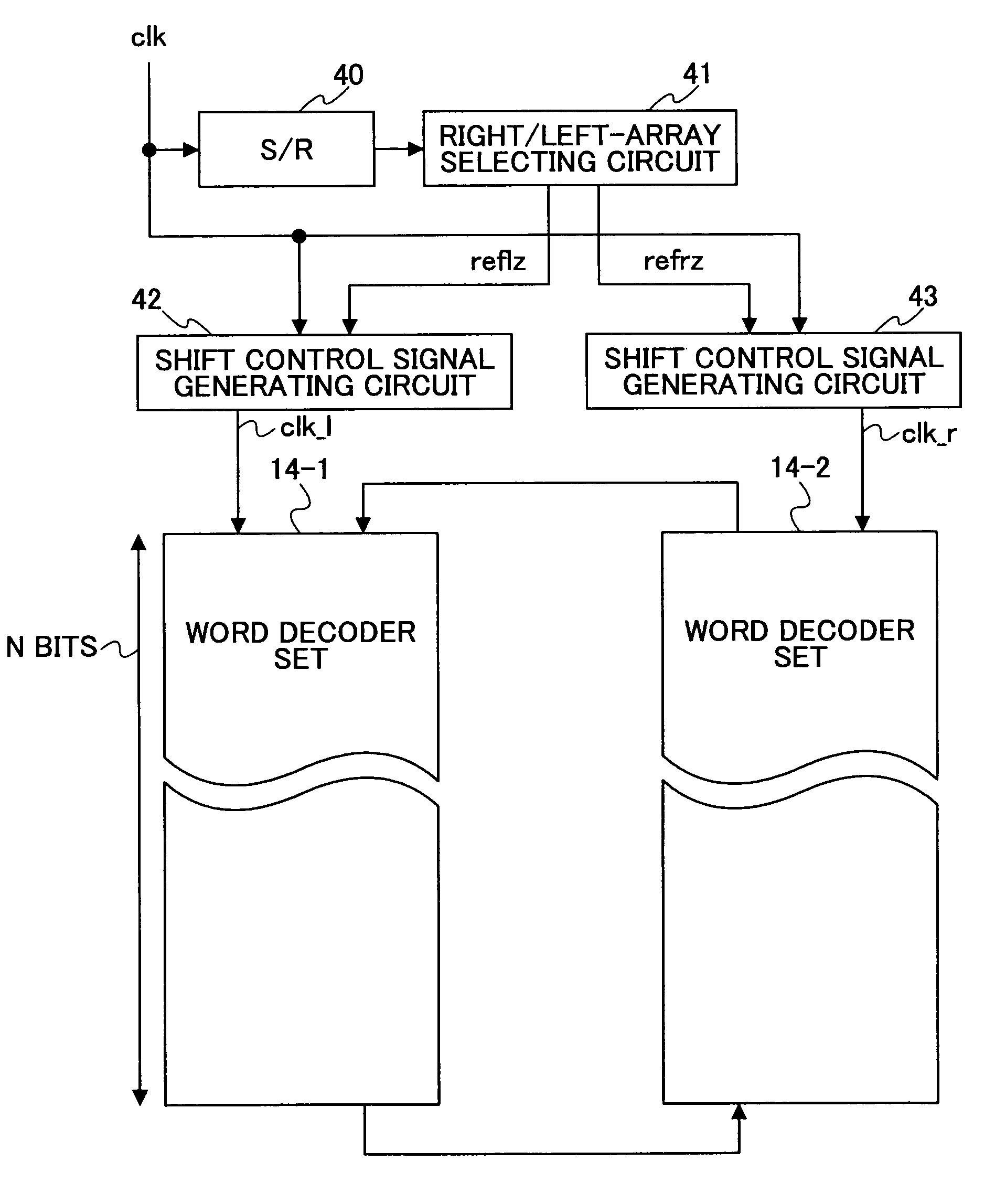
[0044]FIG. 3 is a diagram showing the construction of a shift register controlling circuit according to the present invention.
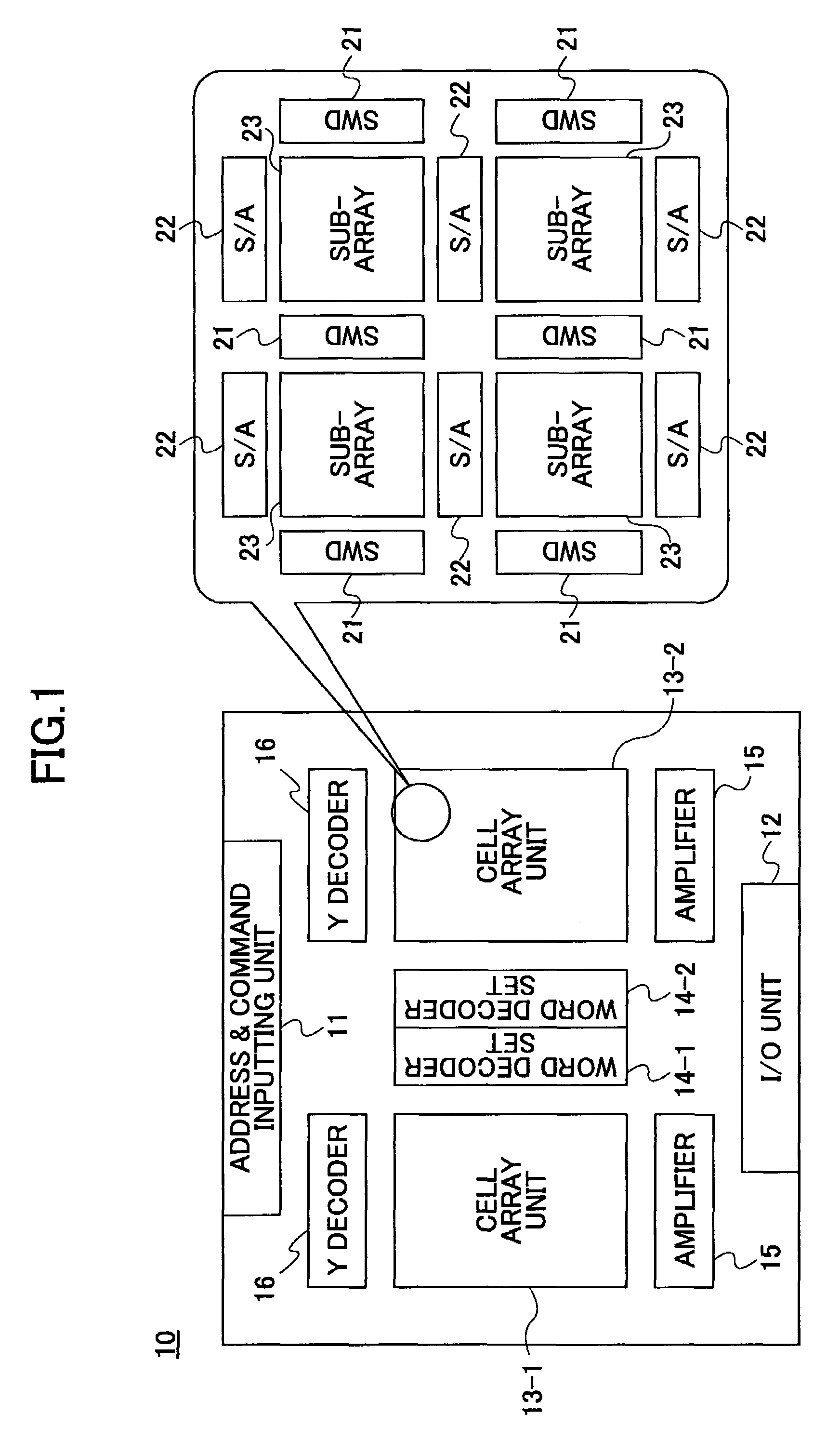
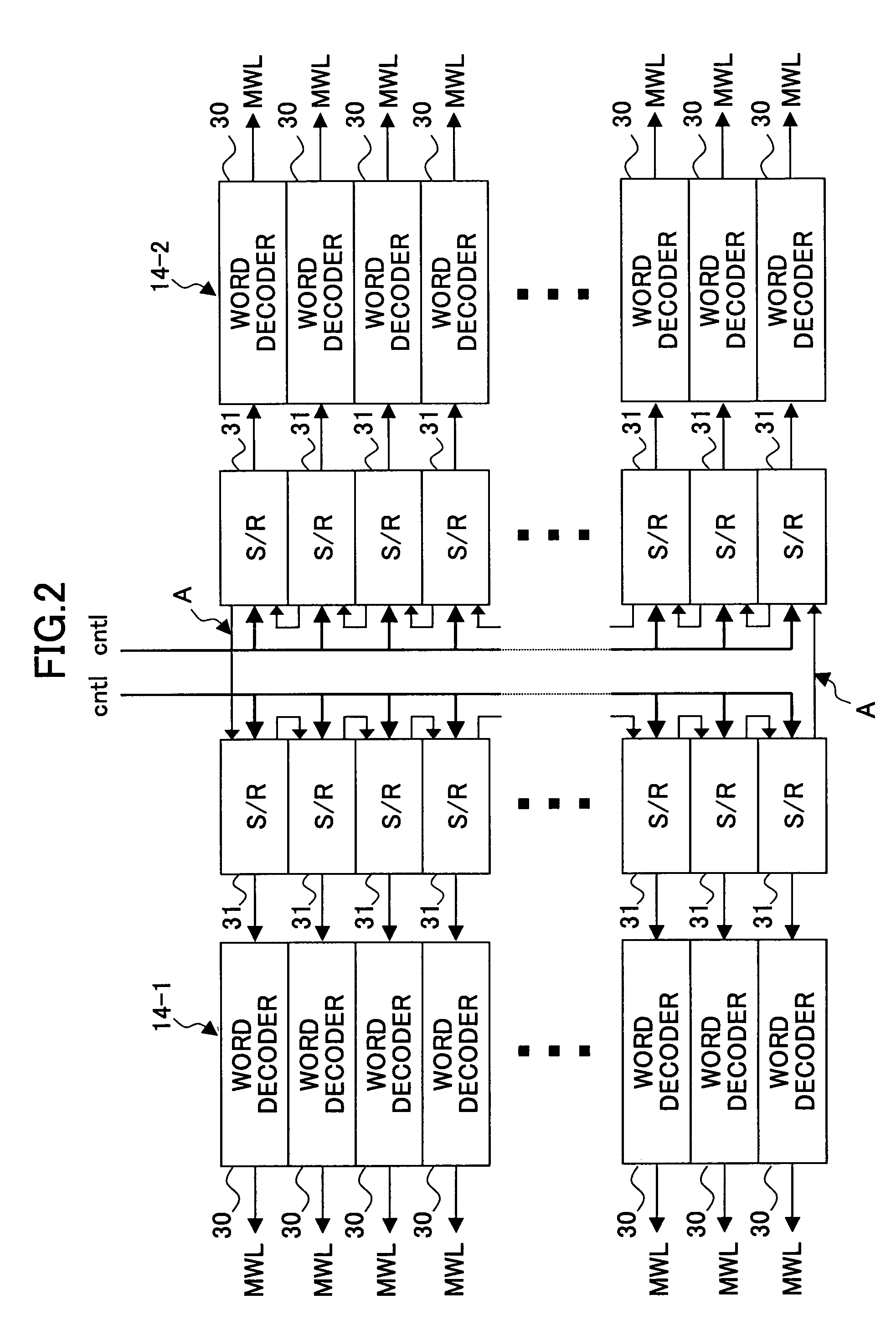
[0045]The shift register controlling circuit of FIG. 3 includes a shift register (S / R) 40, a right / left-array selecting circuit 41, a shift control signal generating circuit 42, and a shift control signal generating circuit 43. The shift control signal generating circuits 42 and 43 generate shift control signals clk—l and clk—r for provision to the word decoder sets 14-1 and 14-2, respectively. The word decoder sets 14-1 and 14-2 are as illustrated in FIG. 1 and FIG. 2. The shift control signal clk—l is supplied as the shift control signal cntl shown in FIG. 2 to the word decoder set 14-1 corresponding to the left-side cell array unit 13-1. The shift control signal clk—r is supplied as the shift control signal cntl shown in FIG. 2 to the word decoder set 14-2 corresponding to the right-side cell array unit 13-2.
[0046]In FIG. 3, the shift register 40 is provid...
second embodiment
[0072]FIG. 11 is a drawing showing the construction of the shift register controlling circuit according to the present invention. In FIG. 11, the same elements as those of FIG. 3 are referred to by the same numerals, and a description thereof will be omitted.
[0073]In the construction shown in FIG. 11, the shift register 40 of the construction shown in FIG. 3 is replaced by a counter-&-decoder circuit 40A. The counter-&-decoder circuit 40A includes a counter for counting up (or counting down) in synchronization with the clock signal clk, and further includes a decoder for decoding the count of the counter. With this provision, it is possible to provide the function equivalent to that provided by the shift register 40. In should be noted that as decoder outputs, only the counter decoded values corresponding to the signals r1, r2, 11, and 12 of FIG. 4 may be output. This makes it possible to implement a decoder by use of a small-scale circuit.
third embodiment
[0074]FIG. 12 is a drawing showing the construction of the shift register controlling circuit according to the present invention. In FIG. 12, the same elements as those of FIG. 3 are referred to by the same numerals, and a description thereof will be omitted.
[0075]In the construction shown in FIG. 12, a check as to which one of the right and left arrays is in the selected state is made by utilizing the outputs of the word line selecting shift registers 82 arranged in the word decoder sets 14-1 and 14-2, rather than using the shift register 40 as in the first embodiment or the counter-&-decoder circuit 40A as in the second embodiment. Specifically, the output of the word line selecting shift register 82 situated at the turning-back point from the left-hand side to the right-hand side is denoted as r1, and the output of the word line selecting shift register 82 situated at the turning-back point from the right-hand side to the left-hand side is denoted as 11. Further, the output of th...
PUM
 Abstract
Description
Claims
Application Information
 - R&D
- Intellectual Property
- Life Sciences
- Materials
- Tech Scout
- Unparalleled Data Quality
- Higher Quality Content
- 60% Fewer Hallucinations
Browse by: Latest US Patents, China's latest patents, Technical Efficacy Thesaurus, Application Domain, Technology Topic, Popular Technical Reports.
© 2025 PatSnap. All rights reserved.Legal|Privacy policy|Modern Slavery Act Transparency Statement|Sitemap|About US| Contact US: help@patsnap.com


