
Vibration-proof structure for metallic electrical packaging case

a technology of electrical packaging and vibration-proof structure, which is applied in the direction of electric propulsion mounting, machine supports, other domestic objects, etc., can solve the problems of generating humming noise, heavy metallic electrical packaging case vibration, and inability to maintain the quiet inside the vehicle, so as to prevent the generation of humming noise, increase the weight of the case, and be easily attached to the vehicle

Inactive Publication Date: 2006-01-24
HONDA MOTOR CO LTD
View PDF13 Cites 17 Cited by
  • Summary
  • Abstract
  • Description
  • Claims
  • Application Information

AI Technical Summary

Benefits of technology

[0006]Accordingly, an object of the invention is to provide a vibration-proof structure for a metallic electrical packaging case by which the generation of humming noise can be surely prevented without increasing the weight of the case, and which may be readily attached to the vehicle.
[0008]According to the above vibration-proof structure for a metallic electrical packaging case, since the metallic electrical packaging case may be supported by the member forming the side wall of the vehicle via the coupling members, the resonance frequency of the high voltage electrical packaging case is increased, and the generation of humming noise due to the structural resonance may be surely prevented. Accordingly, quietness in the interior of the vehicle may be surely maintained.
[0009]Also, according to the above coupling members connecting the outer wall of the metallic electrical packaging case, which may be placed at the rear portion of the interior of the vehicle, the coupling members enable to avoid increasing the weight thereof and making narrow the interior space of the vehicle.
[0011]According to the above vibration-proof structure for a metallic electrical packaging case, it becomes possible to temporarily fix the coupling members readily and surely to the assembly position thereof by engaging the engaging portion formed on one end of the coupling member with the outer wall of the metallic electrical packaging case or the member forming the side wall of the vehicle, and sliding and engaging the insertion engaging portion formed at the other end of the coupling member with the member forming the side wall of the vehicle or the outer wall of the metallic electrical packaging case. Accordingly, the assembling process for the coupling member may be readily carried out.
[0013]According to the above vibration-proof structure for a metallic electrical packaging case, it becomes possible to reduce the size of the coupling members by effectively utilizing the wheel houses, which extend towards the inside the vehicle and are located in the vicinity of the high voltage electrical packaging case. Accordingly, increase in weigh of the vehicle may be prevented.

Problems solved by technology

However, if such a large metallic electrical packaging case is simply placed in the vehicle, the heavy metallic electrical packaging case may vibrate due to the vibration caused by the engine or by running on the road, and humming noise is generated from the electrical packaging case.
Accordingly, there is a problem that the quietness inside the vehicle cannot be maintained.
Also, although it is conceivable to improve the rigidity of the metallic electrical packaging case by increasing the thickness of a plate forming the outer wall of the case in order to prevent the humming noise, this leads to a significant increase in the weight of the case.

Method used


Image

  • Vibration-proof structure for metallic electrical packaging case
  • Vibration-proof structure for metallic electrical packaging case
  • Vibration-proof structure for metallic electrical packaging case

Examples


Embodiment Construction

[0026]The invention summarized above and defined by the enumerated claims may be better understood by referring to the following detailed description, which should be read with reference to the accompanying drawings. This detailed description of particular preferred embodiments, set out below to enable one to build and use particular implementations of the invention, is not intended to limit the enumerated claims, but to serve as particular examples thereof.

[0027]Hereinafter, the vibration-proof structure for a metallic electrical packaging case according to an embodiment of the present invention will be described with reference to the accompanying drawings.

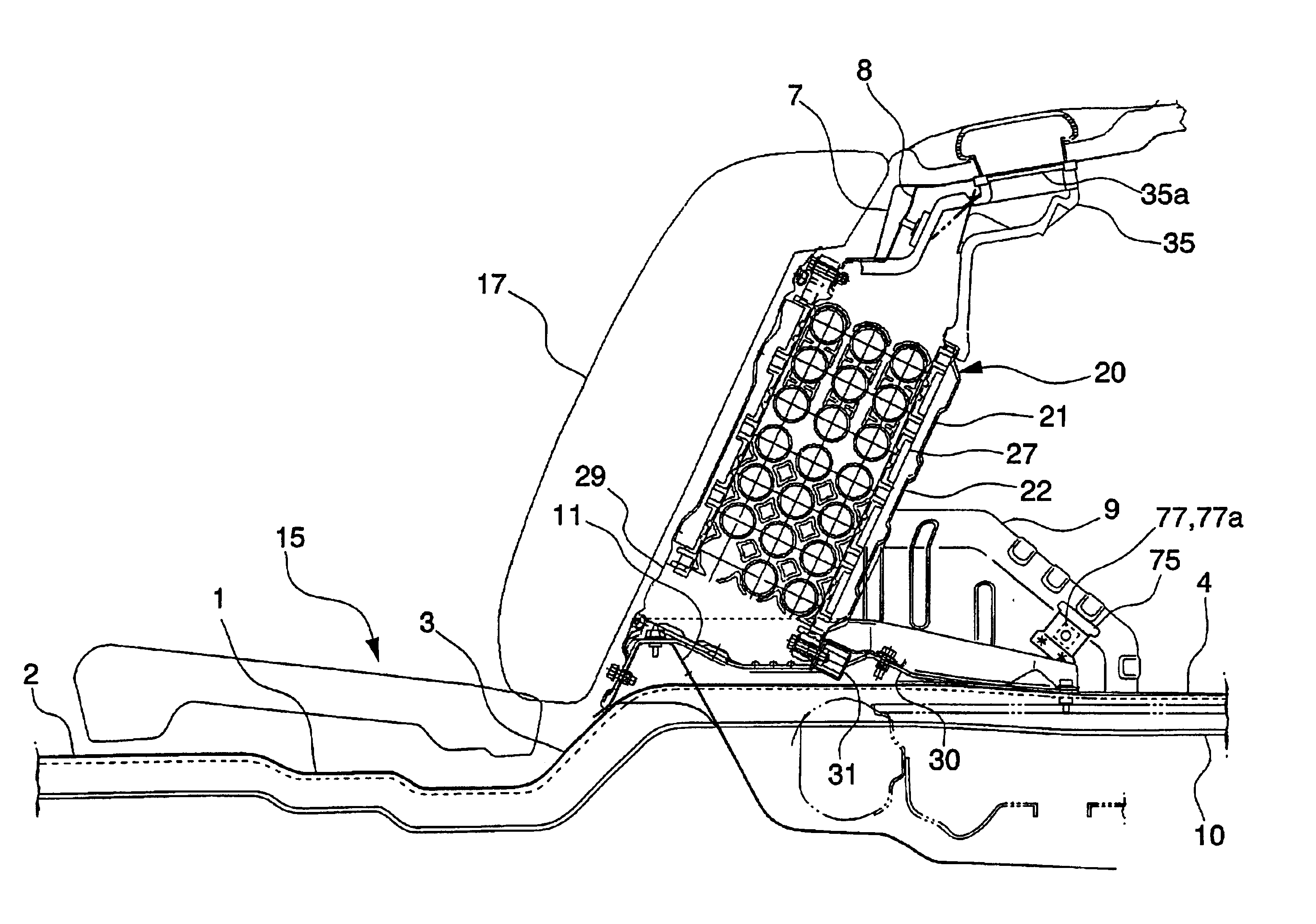
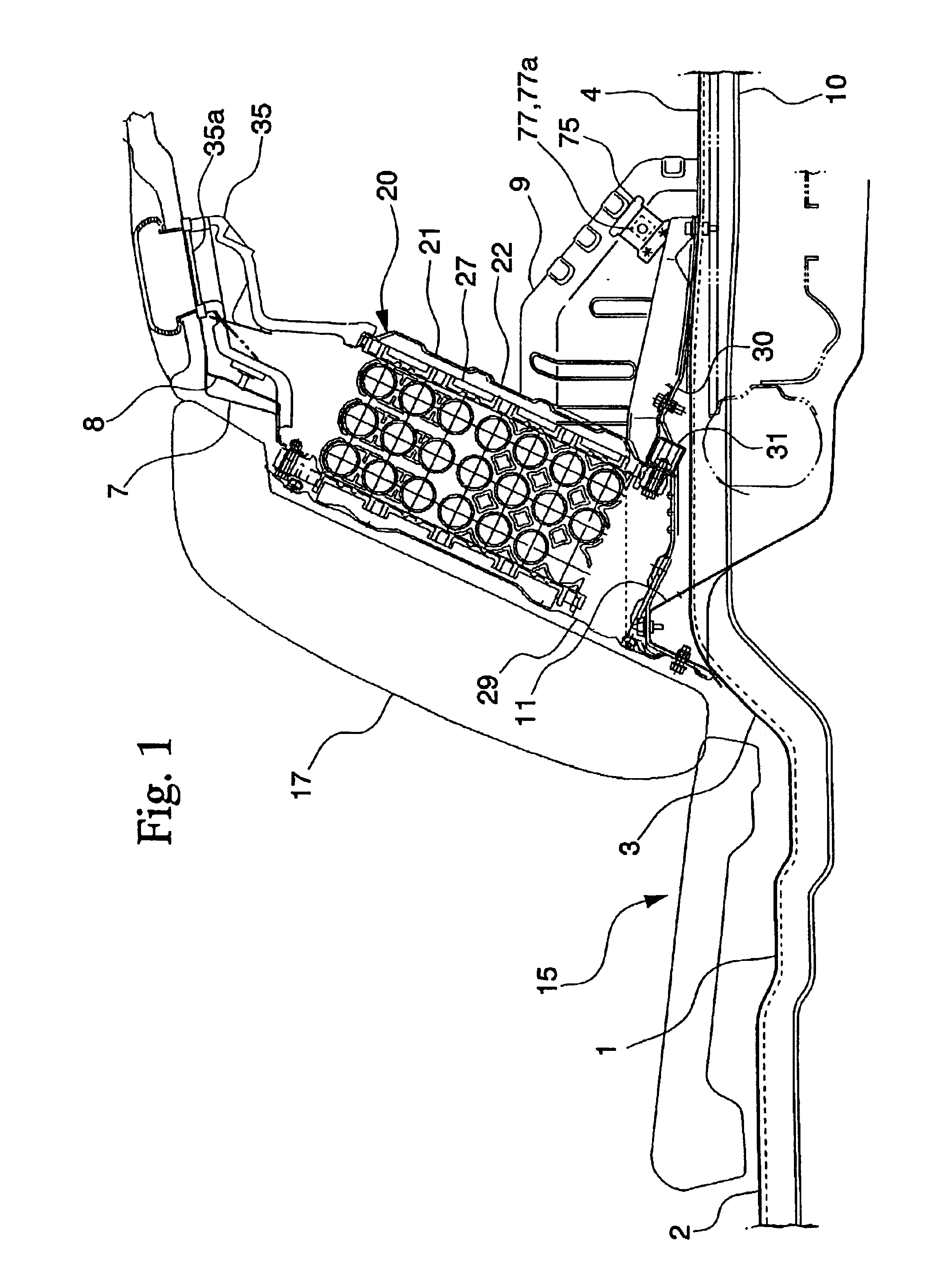
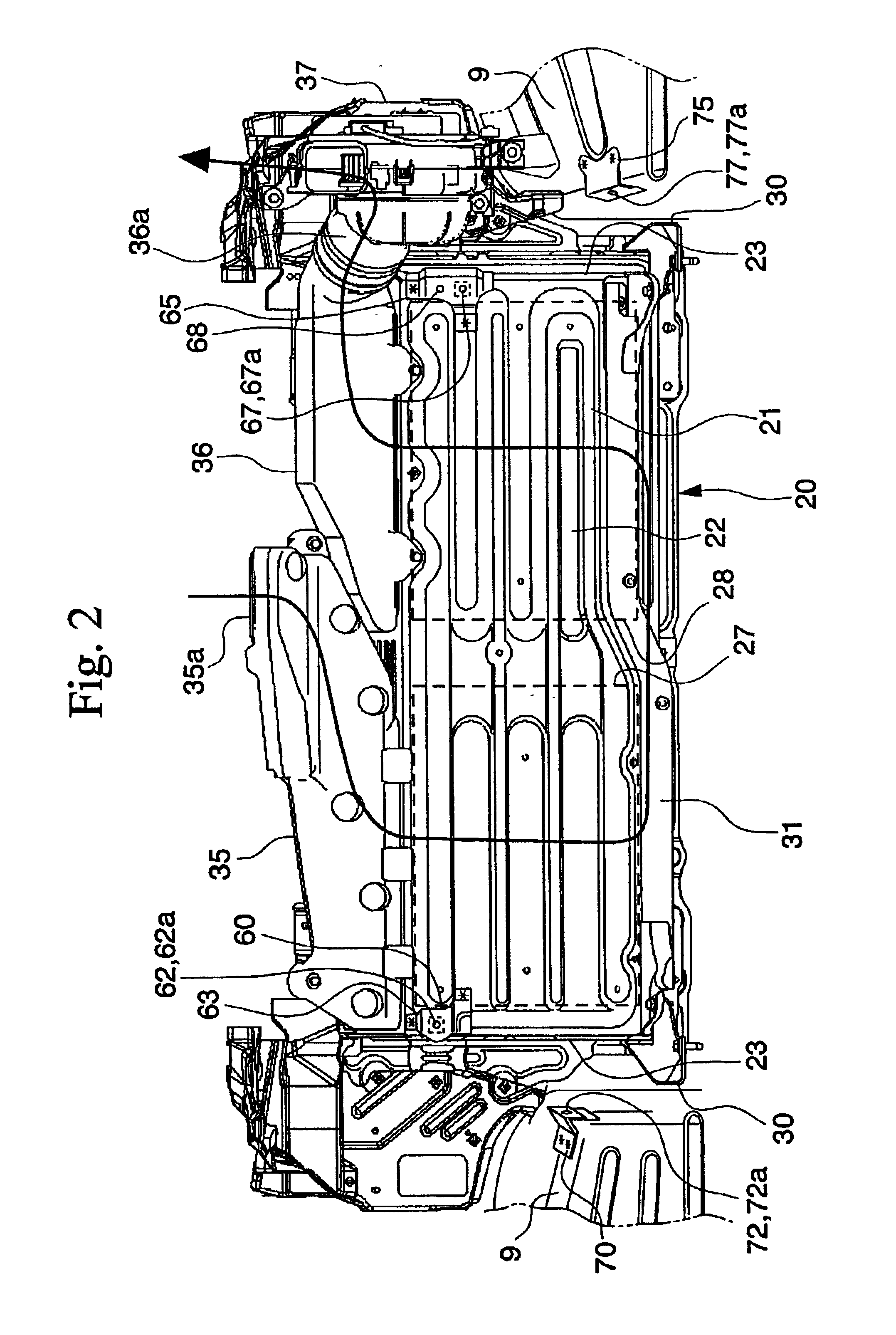
[0028]FIG. 1 is a schematic diagram for explaining a side view of a hybrid vehicle to which a vibration-proof structure for metallic electrical packaging case according to the embodiment of the present invention is applied. As shown in FIG. 1, a floor panel 1 includes a trunk floor 4 which extends upwardly from an interior floor ...


PUM


Abstract

A vibration-proof structure for a metallic electrical packaging case includes a metallic electrical packaging case and a coupling member. The coupling member connects an outer wall of the metallic electrical packaging case and a member forming a side wall of a vehicle. Also, the coupling member may include an engaging portion at one end of the coupling member, which is used for temporarily fixing the coupling member, and an insertion engaging portion, which is engaged with a portion of the member forming the side wall of the vehicle, formed at another end of the coupling member.

Description

BACKGROUND OF THE INVENTION[0001]1. Field of the Invention[0002]The present invention relates to a vibration-proof structure for a metallic electrical packaging case in which high voltage electronic parts used for hybrid vehicles, for example, may be accommodated. More specifically, the present invention relates to a vibration-proof structure for a metallic electrical packaging case by which quietness in the interior of a vehicle may be maintained.[0003]2. Description of Related Art[0004]Vehicles, such as hybrid vehicles, in which the engine is driven being assisted by the motor and the motor is used as a generator during deceleration to collect electric power, are conventionally known. Such vehicles are normally provided with large high voltage electrical parts, for instance, a battery and an inverter, exclusive to the vehicles, and various contrivance have been made for the arrangement of these electronic parts. It is effective to utilize available space in the vehicle for the arr...

Claims


Application Information

Patent Timeline
IPC IPC(8): B60R16/04B60R16/02B60K1/04B60R99/00F16F15/02
CPCB60K1/04B60K2001/005
Inventor TAKEDOMI, HARUMIHASEGAWA, OSAMUMATSUOKA, TOSHIYUKI
Owner HONDA MOTOR CO LTD
Learn More