Displacement and force sensor

a displacement sensor and displacement technology, applied in the direction of material strength using steady bending force, material strength using steady torsional force, etc., can solve the problems of inability to obtain temporal displacement and force history, soil dynamic characteristics vary with soil composition and depth, and cannot be reliably measured at various depths below the surface of an area of soil, etc., to achieve low cost, sensitive

Inactive Publication Date: 2006-01-24
UNIVERSITY OF SASKATCHEWAN
View PDF5 Cites 5 Cited by
  • Summary
  • Abstract
  • Description
  • Claims
  • Application Information

AI Technical Summary

Benefits of technology

[0018]It is an object of the present invention to provide an apparatus for measuring the displacement of particulate or visco-elastoplastic media, such as soils, beneath the surface thereof in response to a force exerted thereon that overcomes problems in the prior art. It is a further object of the present invention to provide such an apparatus that is sensitive, reliable and relatively low cost for sensing and measuring force and displacement time profiles in varying conditions of particulate or visco-elastoplastic media such as soils, at various depths and under various loading conditions.
[0019]It is a further object of the present invention to provide a device useful to determining physical parameters of soils, applicable to the design of safe and effective programs for detonation of landmines in situ.

Problems solved by technology

Measuring actual displacement at various depths below the surface of an area of soil in response to forces exerted on the surface is conventionally difficult and time consuming.
It is often assumed, for practical purposes, that observed surface deflections are cumulative effects of subsurface compactions, however, it is known that soil dynamic characteristics vary with soil composition and depth and are nonlinear.
Further, using previously available technology, temporal displacement and force history is not obtainable.
Thus the available procedures for displacement measurements are slow, labor intensive, and inaccurate, and there is no known method of measuring soil displacement over time.
Inadvertent detonation of landmines in former conflict regions causes injury and death daily.
Landmines are a major socioeconomic factor that adversely affects countries' abilities to recover from the effects of armed conflict.
The presence of landmines at unknown locations in soils disrupts normal trade and commercial activities, access to schools, social services, water and land resources, and other services, and resources sought by people.
Usually, forces exerted to the surfaces of soils by people stepping thereon are insufficient to cause detonation of the explosive materials of antitank or antivehicle mines.
Also, it is known that antitank and antivehicle mines typically comprise sufficient masses of metallic structures to permit detection of such landmines by known remote metal-detection means whereas many antipersonnel mines comprise little metallic mass and cannot be detected efficiently by such means.
However, the number of antipersonnel mines deployed far exceeds the number of antivehicle and antitank mines combined, and the preponderance of death, injury, and other loss caused by inadvertent landmine detonations is attributable to antipersonnel mines.
Similarly in very loose soils the surface force may be dissipated through the soil prior to reaching the landmine, with the result that there is not sufficient force on the upper structure to overcome the resisting bias force and displace the upper structure.
In some cases the loose soil may actually flow around the landmine—there is sufficient displacement but insufficient force.
As discussed above, present technology does not provide for convenient measurement of soil displacement and forces over time.
Furthermore, such known devices as load cells for measuring force alone are expensive and can be easily damaged by the large magnitude impulse forces exerted by landmine detonating equipment.
Heavy equipment operating over the soil surface can cause changes in soil dynamic characteristics, including the formation of subsurface compaction that can affect water retention capacity, penetrability, and other characteristics related to agricultural yields.

Method used


Image

  • Displacement and force sensor
  • Displacement and force sensor
  • Displacement and force sensor

Examples


Embodiment Construction

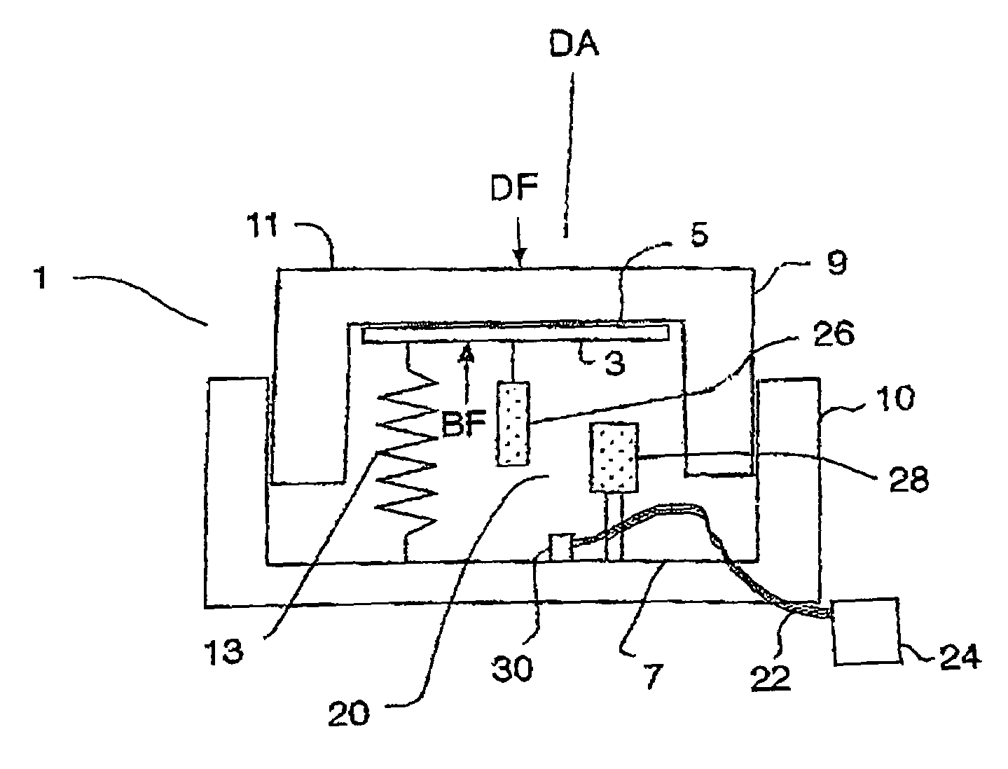
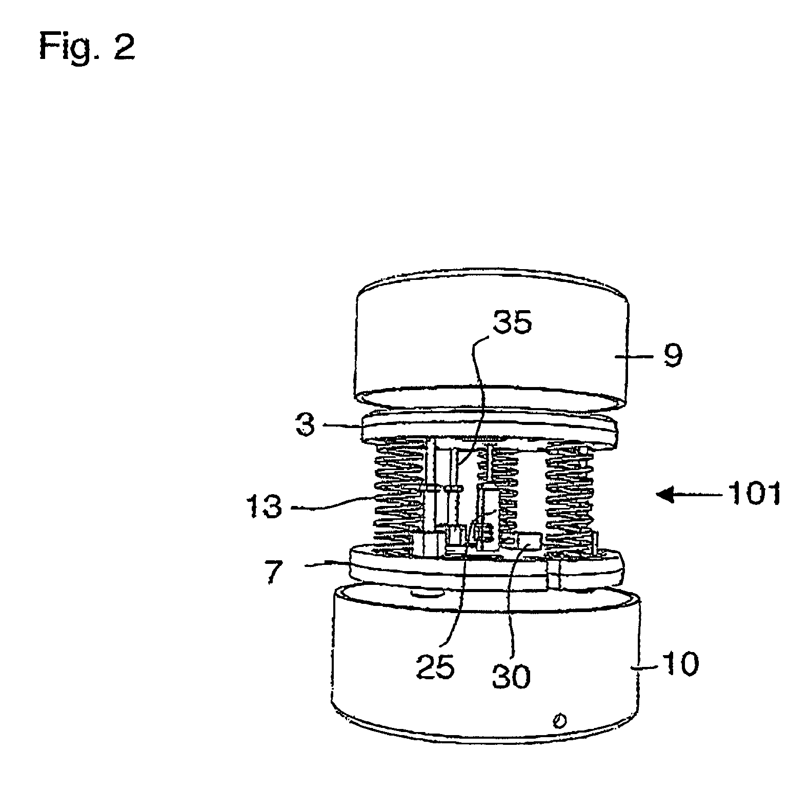
[0030]FIG. 1 schematically illustrates an apparatus 1 of the invention for measuring the displacement of visco-elastoplastic media, such as soils, below the surface thereof. The apparatus 1 comprises an upper plate 3 having a top surface 5 and mounted in the apparatus 1 such that a displacement force DF exerted on the top surface 5 will move the upper plate 3 a displacement distance downward toward a base 7. To enclose and protect the sensing components, the apparatus 1 includes a casing assembly comprising an upper casing member 9 telescoping with respect to a lower casing member 10. The upper plate 3 is fixed to the upper casing member 9 such that a force DF exerted on the top surface 11 of the upper casing member 9 is directly transferred to the top surface 5 of the upper plate 3 and thus pushes the upper plate downward toward the base 7. In the illustrated embodiment the lower casing member 10 also provides the base 7.

[0031]In addition to enclosing and protecting the sensing com...


PUM

PropertyMeasurementUnit
displacementaaaaaaaaaa
forceaaaaaaaaaa
depthaaaaaaaaaa

Abstract

An apparatus for measuring the displacement of visco-elastoplastic media below a surface thereof comprises an upper plate mounted such that a displacement force exerted on the top surface thereof will move the upper plate a displacement distance downward toward a base. Guides maintain the upper plate and the base in alignment such that movement is along a displacement axis. A calibrated bias element exerts a calibrated bias force resisting movement of the upper plate toward the base. A displacement measuring device measures the displacement distance, and is operative to generate a movement signal corresponding to the displacement distance. A data acquisition system is operative to receive and record the movement signal, and calculate the displacement force exerted on the top surface of the upper plate required to move the upper plate the displacement distance against the calibrated bias force.

Description

[0001]The present invention relates to a device for conveniently measuring displacement profiles beneath the surface of particulate or visco-elastoplastic media such as soils, in response to forces transferred through and in the media.BACKGROUND OF THE INVENTION[0002]Measuring actual displacement at various depths below the surface of an area of soil in response to forces exerted on the surface is conventionally difficult and time consuming. Conventionally, an indicator, such as a flexible film or a layer of powder, is placed between layers of soil. The desired load or force is applied to the soil surface, and the soil is excavated and displacement of the indicators is measured.[0003]Such a process requires that soil be excavated from a hole and the soil placed back in the hole with indicators between layers. In a lab setting, soil and indicators can be layered in a box.[0004]Soils are complex media comprising particulate solids, liquids and gases that can be modeled as visco-elasto...

Claims


Application Information

Patent Timeline
Patent Type & Authority Patents(United States)
IPC IPC(8): G01N3/02E02D5/00E21B49/00G01B5/00G01B21/00G01L1/00G01N19/00G01N33/24
CPCG01N33/24G01L1/005
Inventor KUSHWAHA, R. LALROTH, LOUISSCHNAIDER, JAMESLLOYD, TYRELROBERTS, WILLIAM C.MORLEY, WAYNESTILLING, DENISE
Owner UNIVERSITY OF SASKATCHEWAN
Why Eureka
Try Eureka