
Orthodontic brace with self-releasing appliances

a self-releasing, brace technology, applied in dental surgery, dental tools, medical science, etc., can solve the problems of elastomeric and metal ligatures that are not entirely satisfied with orthodontic braces, disadvantages of elastomeric and metal ligatures, and time-consuming installation of ligatures, so as to achieve the effect of improving orthodontic braces

Active Publication Date: 2006-01-10
3M INNOVATIVE PROPERTIES CO
View PDF58 Cites 30 Cited by
  • Summary
  • Abstract
  • Description
  • Claims
  • Application Information

AI Technical Summary

Benefits of technology

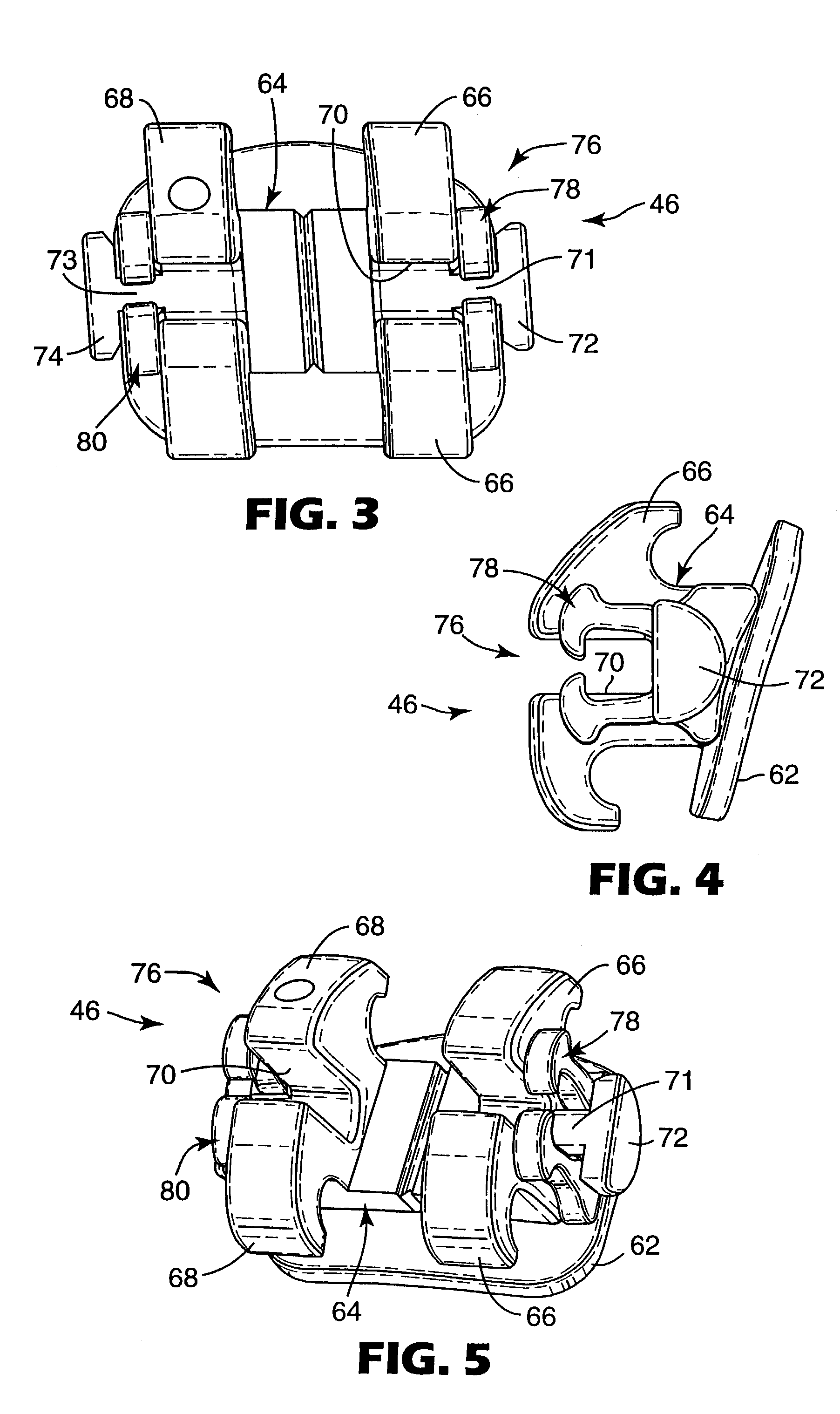
[0023]The present invention is directed toward improvements in orthodontic braces that comprise appliances having a self-releasing latch. The latch of each appliance releases the archwire from the archwire slot whenever the archwire exerts a force on the latch that exceeds a certain value. Advantageously, this certain value (or “release value”) is higher for certain appliances in comparison to other appliances along the dental arch, so that it is less likely that the archwire is inadvertently released even in instances of severe malocclusions.
[0024]Moreover, the efficiency of an orthodontic treatment program may be enhanced when certain teeth are subjected to higher levels of force than the force exerted on other teeth. For example, teeth located in posterior regions of the oral cavity have, in general, larger roots than the roots of teeth located in anterior regions. To maintain approximately the same stress / strain distribution in the periodontal ligament along the dental arch and rate of movement of the teeth, higher forces will, in general, be needed for the larger posterior teeth in comparison to the anterior teeth. Consequently, it is beneficial in certain instances to construct the latch of posterior appliances to provide a higher release value than the release value of anterior appliances.
[0025]Varying the release value from one appliance to another provides other advantages as well. For example, the practitioner may elect to limit the maximum amount of force exerted on a tooth by an archwire, as determined by the release value of the latch, so that the periodontal ligament responds to movement of the root or roots in the most effective manner. Limiting the release value also serves to limit the amount of pain that might be experienced by the patient. Additionally, a higher release value may be desired for appliances located next to orthodontic force modules (such as Class II or Class III correctors) that tend to exert a force on the archwire.

Problems solved by technology

Unfortunately, some orthodontists are not entirely satisfied with elastomeric and metal ligatures.
Such ligatures are somewhat time-consuming to install, both during initial installation and also during reinstallation whenever replacement of the archwire or ligatures is desired.
Other disadvantages are also associated with elastomeric and metal ligatures.
For example, there have been reports that certain polyurethane elastomeric ligatures have exhibited deformation and force decay during the course of treatment.
In some instances, elastomeric ligatures are stained by food and beverages consumed by the patient and become somewhat unsightly.
Metal ligatures often have sharp ends that may retain plaque and food debris and also may increase the risk of infection.
However, certain orthodontic patients have teeth that are severely maloccluded.
For example, one tooth along the dental arch may be significantly out of alignment with neighboring teeth.
As another example, one of the teeth may have shifted in a rotative direction about its long axis to an unsatisfactory orientation.
Moreover, one or more teeth may be both out of alignment and rotated about their long axes.
Such malocclusions are considered unaesthetic and may adversely affect the normal function of the teeth during mastication.
In some cases, this localized bending can greatly increase the force of the archwire against the latch to such a degree that the latch opens and releases the archwire.
However, inadvertent release may occur again in the future unless the orthodontist replaces the archwire with an archwire having less stiffness, or alternatively uses a ligature to help secure the archwire in the archwire slot.
In either case, the advantages of these appliances are compromised.

Method used


Image

  • Orthodontic brace with self-releasing appliances
  • Orthodontic brace with self-releasing appliances
  • Orthodontic brace with self-releasing appliances

Examples


Embodiment Construction

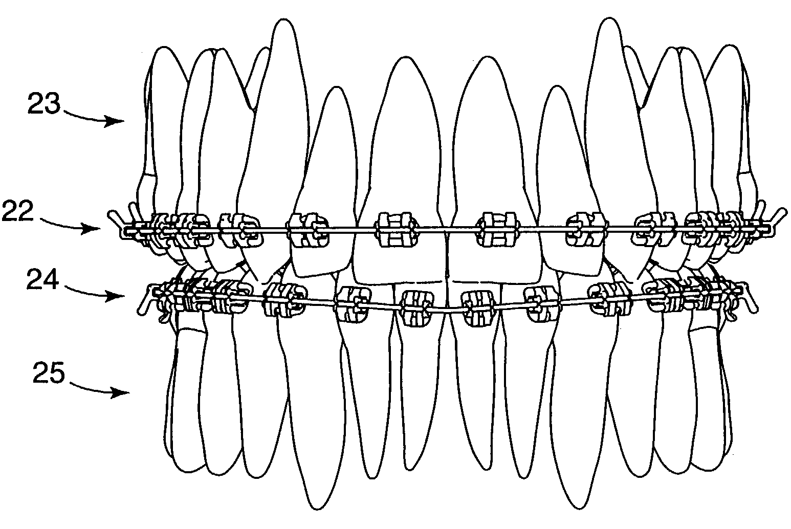
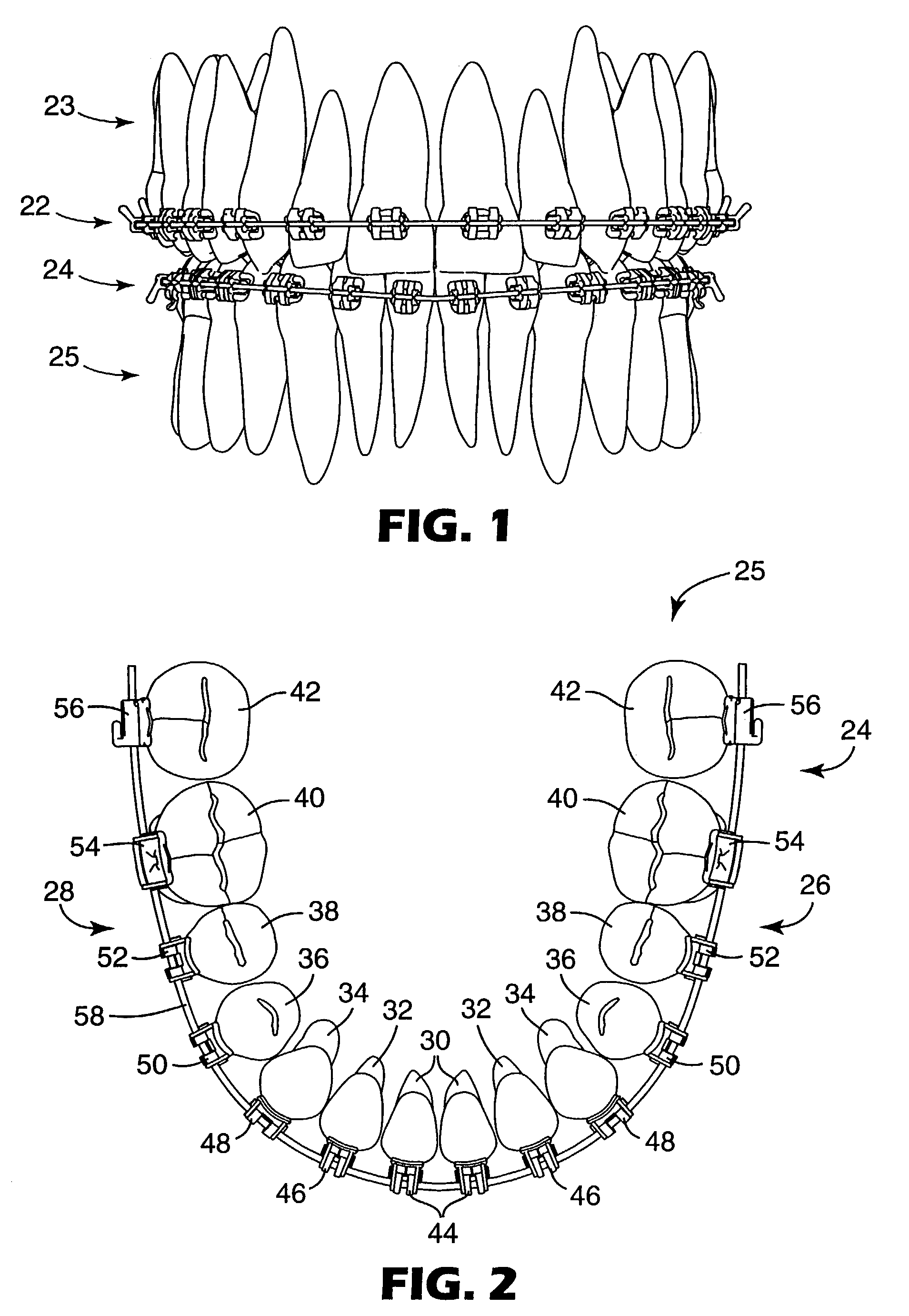
[0042]FIG. 1 illustrates an example of an oral cavity of an orthodontic patient who is undertaking orthodontic therapy. The patient has a first orthodontic brace 22 that is connected to the teeth of the upper dental arch 23 and a lower orthodontic brace 24 that is connected to the teeth of the lower dental arch 25. Each brace 22, 24 includes a set of orthodontic appliances along with an archwire that is received in slots of the appliances, as will be described in more detail below.

[0043]FIG. 2 is an enlarged view of the lower dental arch 25 along with the lower brace 24, looking in a downwardly direction toward the outer or occlusal tips of the teeth. The lower dental arch includes a left quadrant 26 and a right quadrant 28. Each of the quadrants 26, 28 includes a central incisor tooth 30, a lateral incisor tooth 32, a cuspid tooth 34, a lower first bicuspid tooth 36 and a second bicuspid tooth 38. In addition, each of the quadrants 26, 28 includes a first molar tooth 40 and a secon...


PUM


Abstract

An orthodontic brace includes a set of appliances that are connected to respective teeth of the patient. At least some of the appliances include a latch that is operable to release an archwire from the appliance whenever the force exerted by the archwire exceeds a certain value. This value is higher for appliances connected to certain teeth than the value associated with appliances connected to other teeth, in accordance with the particular malocclusion encountered. The brace is constructed to ensure that the goals of the treatment program are carried out in an efficient manner while reducing the likelihood of inadvertent release of the archwire during the course of treatment.

Description

BACKGROUND OF THE INVENTION[0001]1. Field of the Invention[0002]This invention relates to a brace or components of a brace used in orthodontic treatment to correct malocclusions. The brace and brace components include orthodontic appliances such as a bracket or buccal tube having a releasable latch for releasably retaining an archwire in an archwire slot of the appliance.[0003]2. Description of the Related Art[0004]Orthodontic therapy is a specialized type of treatment within the field of dentistry, and involves movement of malpositioned teeth to orthodontically correct locations. Orthodontic treatment often improves the patient's occlusion and typically enhances the aesthetic appearance of the teeth.[0005]Many types of orthodontic treatment programs involve the use of a set of tiny appliances and wires that are commonly known collectively as “braces”. During such treatment programs, small appliances known as brackets are fixed to the patient's anterior, cuspid and bicuspid teeth, a...

Claims


Application Information

Patent Timeline
Patent Type & Authority Patents(United States)
IPC IPC(8): A61C3/00A61C7/28A61C7/30
CPCA61C7/30A61C7/28
Inventor LAI, MING-LAI
Owner 3M INNOVATIVE PROPERTIES CO
Learn More