Coupling for connecting hydraulic ducts

a technology for connecting hydraulic ducts and hydraulic ducts, which is applied in the direction of couplings, pipe elements, mechanical equipment, etc., can solve the problems of high mechanical loading of plastic rings, cumbersome assembly, and inability to hold the residual locking elements, and achieve the effect of few components and easy pre-assembling

Inactive Publication Date: 2006-01-10
WALTERSCHEID ROHRVERBINDUNGSTECHN +1
View PDF22 Cites 21 Cited by
  • Summary
  • Abstract
  • Description
  • Claims
  • Application Information

AI Technical Summary

Benefits of technology

The present invention provides a coupling for hydraulic ducts that has a simple construction and is easy to assemble. The coupling has two main components: a female coupling and a male coupling. The female coupling has a receptacle with a locking face and a holding element with a spring element. The male coupling has a receptacle and a male coupling element with a locking face. The two coupling elements can be easily connected together by inserting the male coupling element into the female coupling. The holding element has a ring with several spring elements that can be deformed radially outward and inward. The holding element also has a second displacement face that interacts with the locking elements. The coupling can be easily disassembled and pre-assembled. The technical effects of the invention are that it provides a reliable and secure coupling for hydraulic ducts, and it is simple and easy to assemble.

Problems solved by technology

A disadvantage in this coupling is that when a locking element is loosened, the residual locking elements are not held in the inner circumferential groove since they cannot support each other.
Furthermore, a high number of components is necessary making the assembly cumbersome.
Furthermore, the plastic ring is loaded by a high mechanical loading.
This causes a jamming of the male coupling during withdrawal.
Furthermore, there is a danger that the circlip may widened irregularly and thus not widened round because it is cut at one position.
A disadvantageous is that the spring elements in the connected condition of the coupling, are tensioned and are correspondingly massively formed.
Furthermore, when releasing the coupling, the unlocking sleeve has to be moved against the withdrawal direction of the male coupling, so that a single-handed operation is not possible.

Method used


Image

  • Coupling for connecting hydraulic ducts
  • Coupling for connecting hydraulic ducts
  • Coupling for connecting hydraulic ducts

Examples


Embodiment Construction

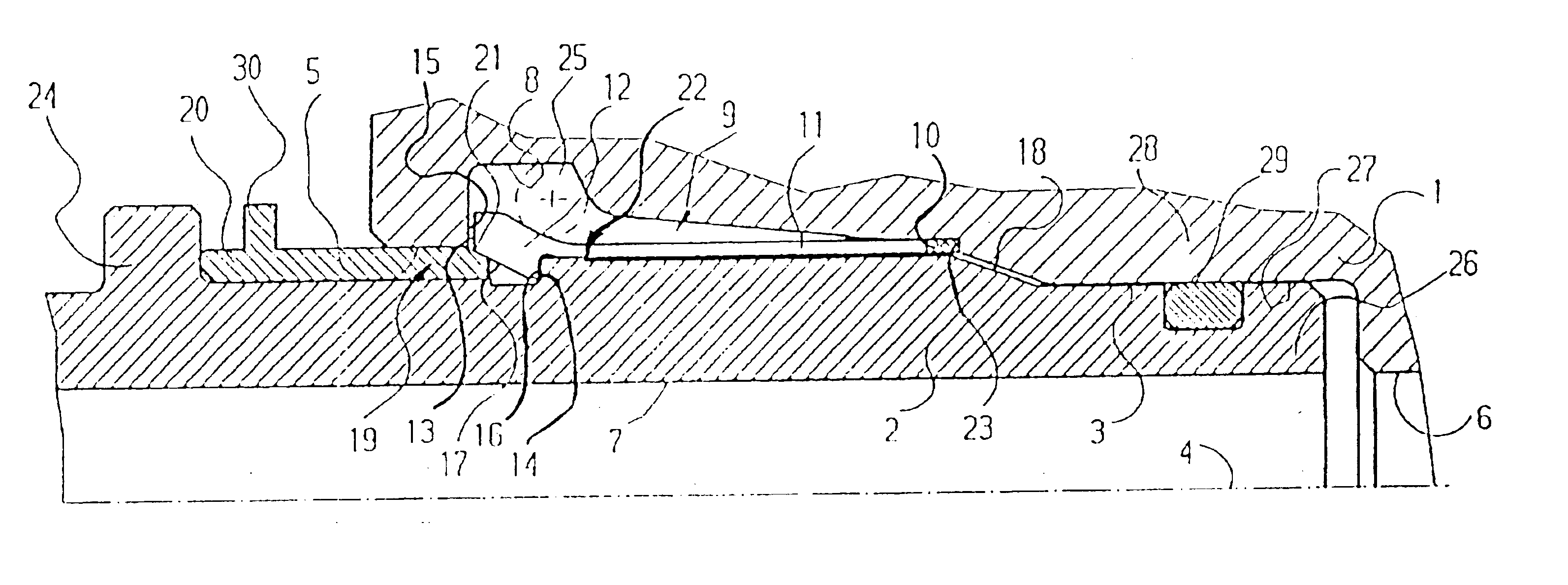
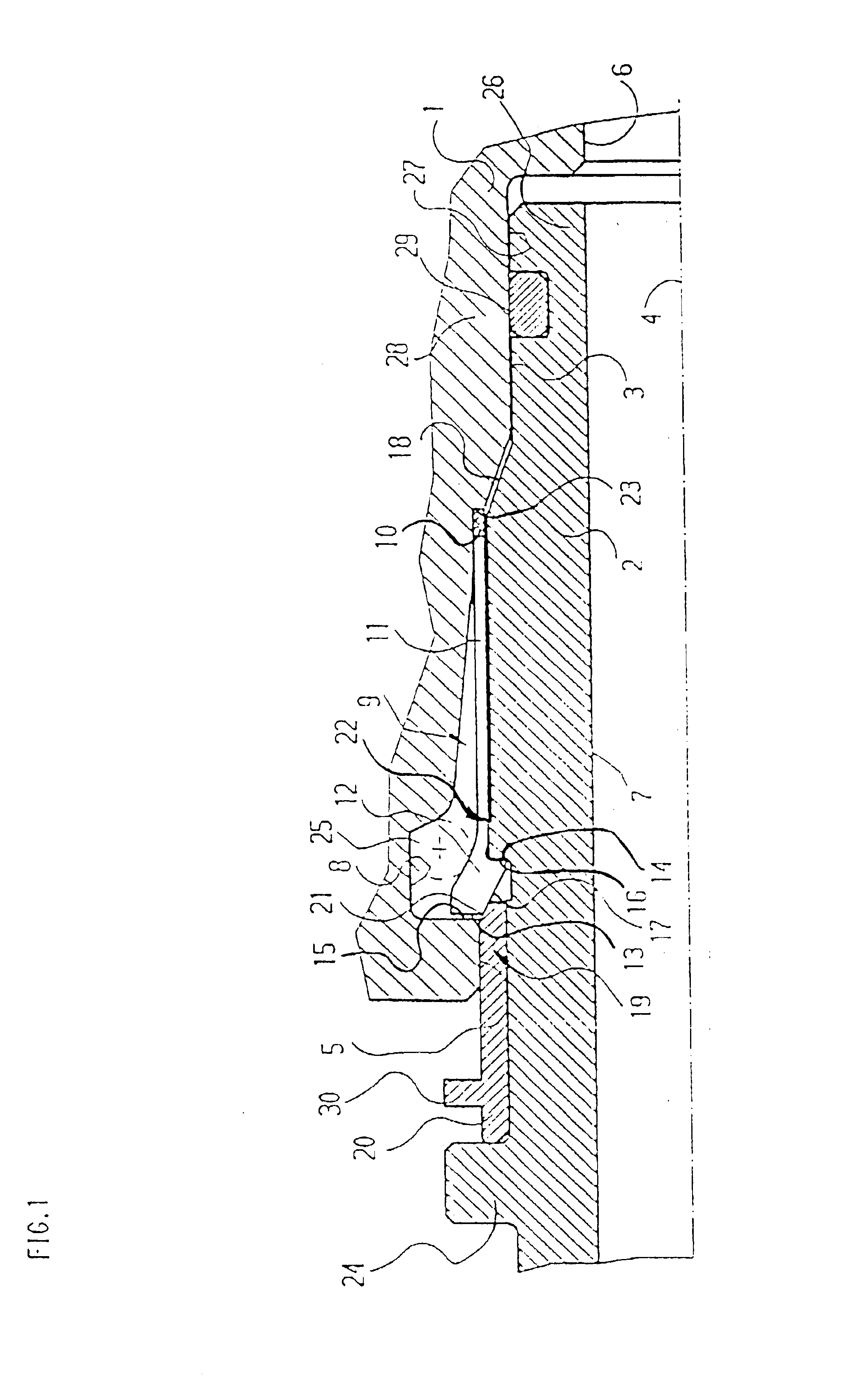
[0053]The following description of the preferred embodiment(s) is merely exemplary in nature and is in no way intended to limit the invention, its application, or uses.

[0054]FIG. 1 shows a coupling for connecting hydraulic ducts according to the invention. A first coupling element 1 is in the form of a female coupling and a second coupling element 2 is in the form of a male coupling. The first coupling element 1 has a receptacle 3. The second coupling element 2 is inserted into the receptacle in the direction of a longitudinal axis 4 through an opening 5. The first coupling element 1 has a first axial bore 6 and the second coupling element 2 has a second axial bore 7. The axial bores 6 and 7, respectively, are connected to hydraulic ducts.

[0055]An annular recess 8 is provided in the receptacle 3 of the first coupling element 1. A holding element 9 rests in the annular recess 8. The holding element 9 has a ring 10 coaxially arranged on the longitudinal axis 4. Axially extending sprin...


PUM


Abstract

A coupling for connecting hydraulic ducts has a female coupling (1) with a receptacle and a first locking face arranged around a longitudinal axis. A male coupling (2) forms a second locking face, arranged around the longitudinal axis. The male coupling (2) can be inserted in the direction of the longitudinal axis (4) through an opening into the receptacle (3). A holding element (9) has a ring (10) with several spring elements projecting from the ring (10). The spring elements (11) extend parallel to the longitudinal axis (4). Locking elements (12) are formed on the free ends of the spring elements (11). The spring elements (11) are, respectively, elastically deformable against a spring force radially out of a locking position into a releasing position. In the inserted condition of the male coupling (2), the first locking face (15) and the second locking (16) face one another. Also, the locking elements (12) are supported in the locking position of the spring elements (11) on the first locking face (15) and on the second locking face (16).

Description

CROSS-REFERENCE TO RELATED APPLICATIONS[0001]This application claims priority to German Patent Application Nos. 10206853.4 filed Feb. 18, 2002, and 10301127.7 filed Jan. 14, 2003 which applications are herein expressly incorporated by reference.FIELD OF THE INVENTION[0002]The present invention relates to a coupling for connecting hydraulic ducts.BACKGROUND OF THE INVENTION[0003]WO 9635906 A1 describes a coupling for hydraulic ducts with a female coupling and a male coupling. The female coupling has a receptacle which receives the male coupling through an opening of the receptacle. The opening includes an inner circumferential groove which receives a multitude of locking elements. The locking elements, in form of annular segments supporting one another, are distributedly arranged around the circumference of the inner circumferential groove. The locking elements are springingly acted upon by an elastic O-ring towards the inside at the end of the inner circumferential groove distanced ...

Claims


Application Information

Patent Timeline
Patent Type & Authority Patents(United States)
IPC IPC(8): F16L37/18F16L37/084F16L37/12
CPCF16L37/0987F16L37/0842
Inventor WOLF, DIETHARDALTENRATH, JORGMACIT, RECEP
Owner WALTERSCHEID ROHRVERBINDUNGSTECHN
Why Eureka
Try Eureka