Imaging apparatus and method of optical-black clamping

a technology of optical black and imaging apparatus, applied in the field of imaging apparatus and method of optical black clamping, can solve the problems of increasing the number of signal-output channels of imaging apparatus, many circuit design restrictions, and stepping outputs, and achieve the effect of accurate cancellation of stepped outputs

Active Publication Date: 2006-01-03
JVC KENWOOD CORP A CORP OF JAPAN
View PDF4 Cites 35 Cited by
  • Summary
  • Abstract
  • Description
  • Claims
  • Application Information

AI Technical Summary

Benefits of technology

[0015]A purpose of the present invention is to provide an imaging apparatus with a solid-state image sensing device and a method of optical-black clamping that achieve accurate cancellation of stepped outputs between right and left in device imaging area divided into two or more.

Problems solved by technology

Such a requirement causes many restrictions on circuit design with noise and radiation suppression.
Such imaging-area division, however, increases the number of signal-output channels for imaging apparatus used in camera-built-in VTRs.
This results in stepped signal fluctuation on the border of the output channels.
The OB-level difference causes inaccurate OB-clamp function due to usage of the average of different OB levels.
This results in difference in black level between right and left in video.
Such a high frequency causes unrectangular pulse waveforms and inefficient charge transfer through many transfer stages.
This results in OB-level differences over rows of pixels, which should not occur ideally.
This reference black-level setting could cause inaccurate black-level adjustments due to level difference between the upper and lower zones in imaging areas.
Known imaging apparatus further suffer small modulated light outputs through several color filters even at no light input.

Method used


Image

  • Imaging apparatus and method of optical-black clamping
  • Imaging apparatus and method of optical-black clamping
  • Imaging apparatus and method of optical-black clamping

Examples


Embodiment Construction

[0032]An embodiment of and modifications to imaging apparatus according to the present invention will be disclosed in detail with reference to the attached drawings.

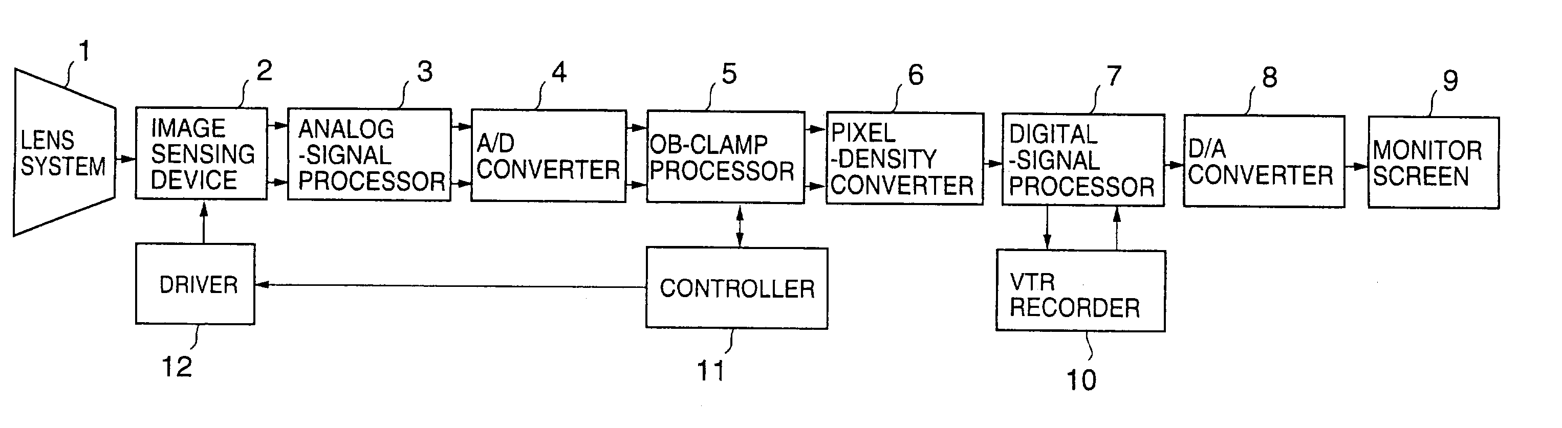
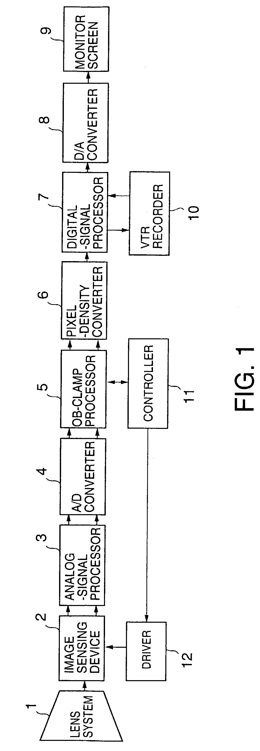
[0033]FIG. 1 is a block diagram of an embodiment of the imaging apparatus used in a camera-built-in VTR.

[0034]Incident light from a target to be imaged and converged through an optical lens system 1 is radiated onto a solid-state image sensing device 2 for photoelectric transfer.

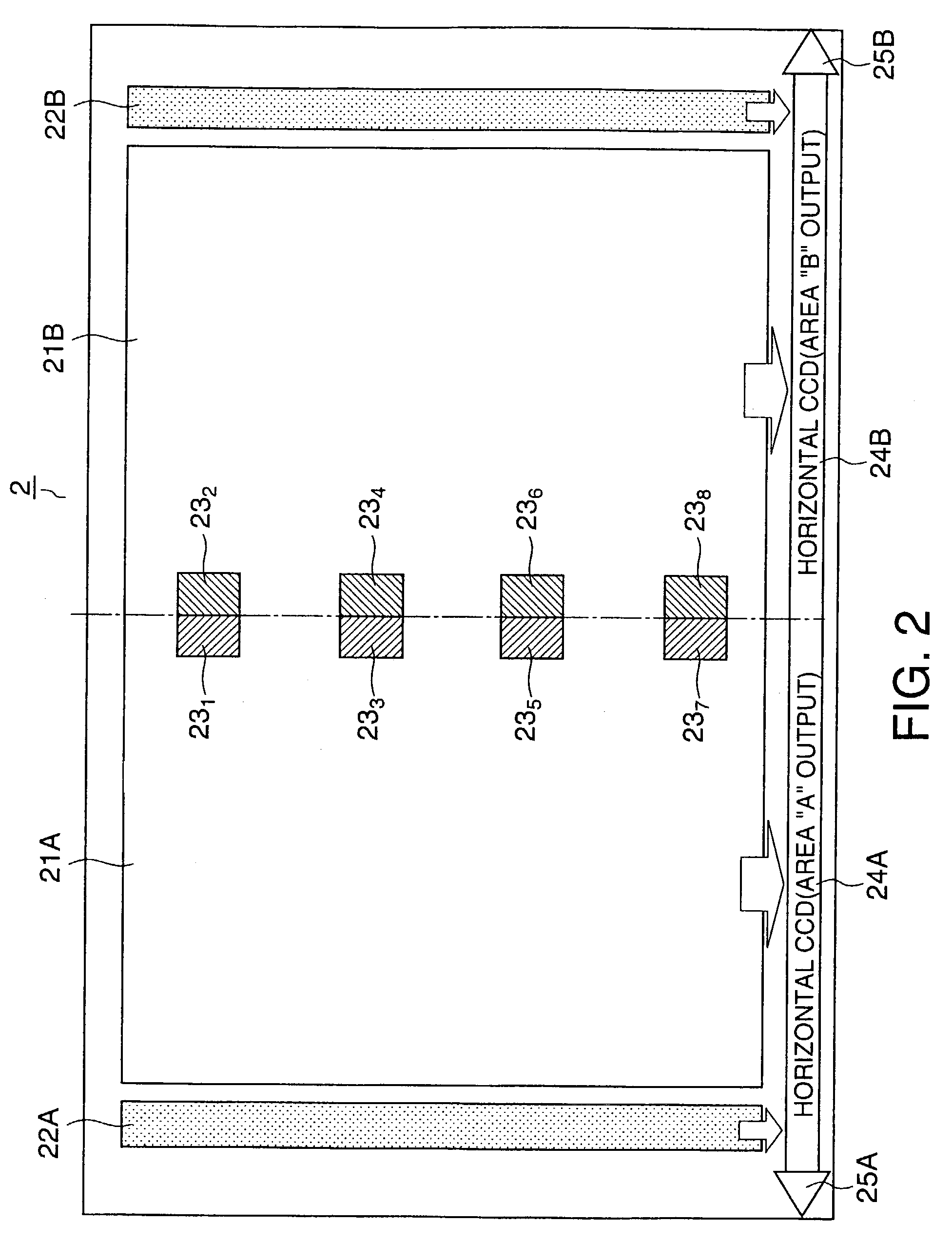
[0035]Illustrated in FIG. 2 is image-area arrangement on the solid-state image sensing device 2.

[0036]The imaging area on the solid-state image sensing device 2 consists of two imaging areas 21A and 21B in left and right, and OB areas 22A and 22B for optical-black-level detection provided on both sides of the imaging areas 21A and 21B.

[0037]The image sensing device 2 is equipped with a horizontal CCD (Charge-Coupled Device) 24A for horizontal transfer of charges transferred from pixels of the imaging area 21A and the OB area 22A through a vertica...


PUM


Abstract

An imaging apparatus has a solid-state image sensing device having an imaging area divided into left and right sub-imaging areas, a first optical-black (OB) area and a second OB area being provided at both edges of the imaging area in the horizontal direction. First video signals are extracted from monitoring areas in the sub-imaging areas close to the border between the sub-imaging areas. Optical-black clamping is applied to second video signals output from the sub-imaging areas by subtracting a first OB signal indicating an OB level in the first OB area from the second video signal output from one of the sub-imaging area and subtracting a second OB signal indicating an OB level in the second OB area from the second video signal output from the other of the sub-imaging areas. Detected first in the optical-black clamping is a level difference between the extracted first video signals. Calculated next is an adjusting value per row of pixels, that provides the smallest level difference per row of pixels in the imaging area based on the detected level difference. The first OB signal is subtracted from one of the second video signals and the second OB signal is subtracted from the other second video signal, thus outputting an optical-black-clamped video signal. Video-signal levels are adjusted by multiplying the optical-black-clamped video signal by the adjusting value.

Description

BACKGROUND OF THE INVENTION[0001]The present invention relates to an imaging apparatus equipped with a solid-state image sensing device having an imaging area divided into at least two areas from which video signals are derived, and a method of optical-black clamping.[0002]With widespread home use of camera-built-in VTRs, gradually spread is a camera-built-in VTR with an electronic still-picture imaging function to process video signals output from a solid-state image sensing device and transfer the processed signals (still-picture data) to several types of equipment, such as personal computers.[0003]The total number of pixels in a solid-state image sensing device has been dramatically increased with development of LSI microfabrication technology.[0004]Most camera-built-in VTRs have an OB (Optical Black)-clamp function.[0005]The OB-clamp function adjusts a black level of a video signal output from a solid-state image sensing device. The clamp function requires rows of several ten bl...

Claims


Application Information

Patent Timeline
Patent Type & Authority Patents(United States)
IPC IPC(8): G09G5/00H04N5/16H01L27/148H04N5/335H04N5/341H04N5/365H04N5/369H04N5/378
CPCH04N5/37213H04N5/361H04N5/165H04N25/63H04N25/713
Inventor KUNIMI, HIROYASUNISHIYAMA, HIROSHIOURA, TETSUYAMIYAHARA, HIROYUKIIBARAKI, TAKESHI
Owner JVC KENWOOD CORP A CORP OF JAPAN
Why Eureka
Try Eureka