
Load sensing applanation tonometer

a tonometer and load sensing technology, applied in the field of medical diagnostic systems, can solve the problems of heightened drawback, relatively few persons with the resources and technical capability to perform periodic calibrations, and goldmann applanation tonometers are susceptible to errors, and achieve the effect of robust performan

Inactive Publication Date: 2006-01-03
J D MUELLER
View PDF21 Cites 15 Cited by
  • Summary
  • Abstract
  • Description
  • Claims
  • Application Information

AI Technical Summary

Benefits of technology

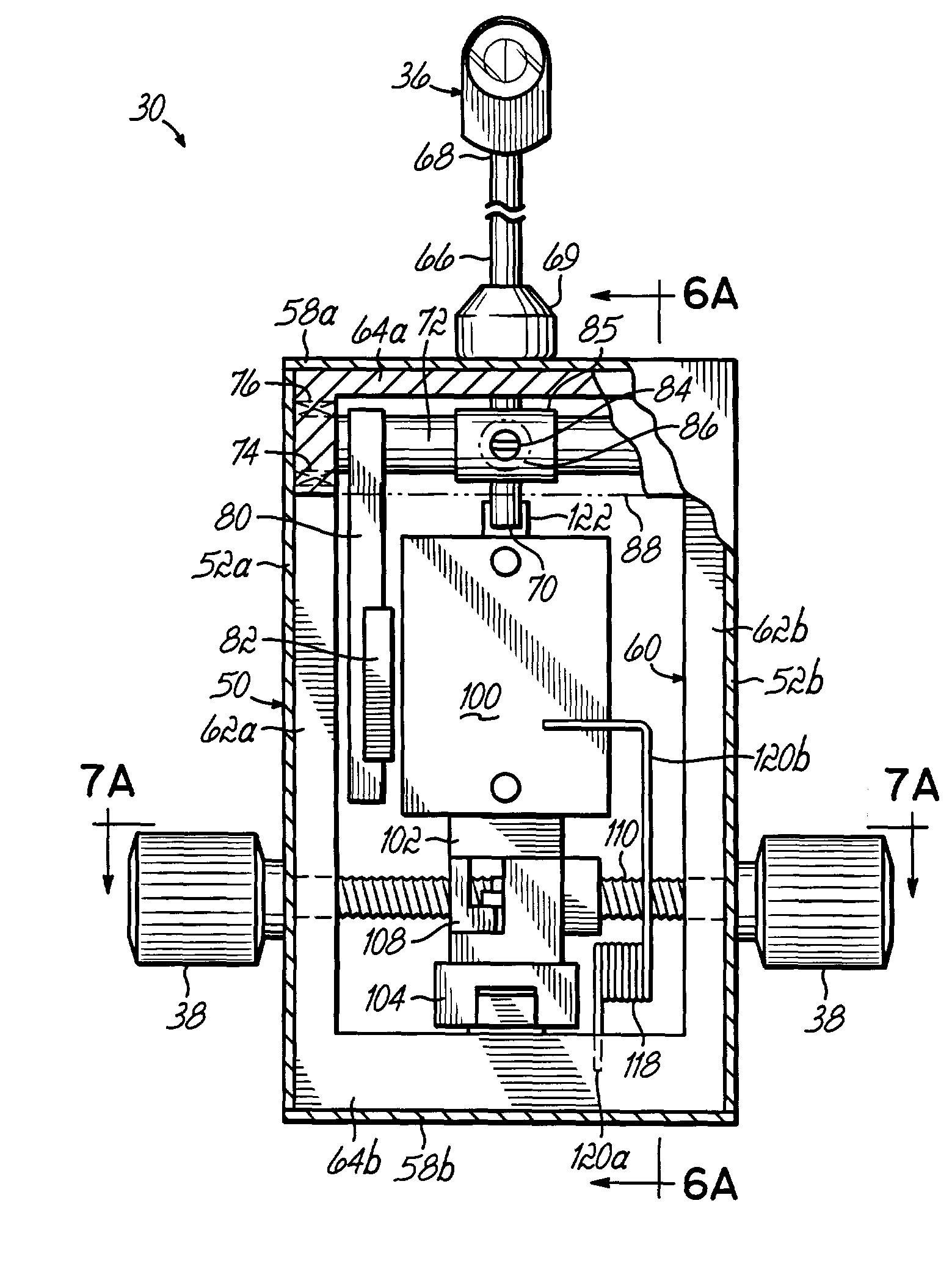
[0006]The present invention overcomes these drawbacks by incorporating into an applanation tonometer a force sensor that is configured to sense the force applied by the probe to the cornea of the patient's eye, and to generate a signal corresponding to the sensed force. This inventive applanation tonometer has an applanation probe containing a prism system that, when viewed through a microscope assembly, generates a visual indication when a desired area of the cornea of a patient's eye has been flattened by the probe. This inventive applanation tonometer can be used with a conventional microscope assembly, such as a biomicroscope slit lamp, in a manner that is familiar to and widely accepted by medical practitioners, to measure the intraocular pressure of a patient's eye. Advantageously, the applanation tonometer of the present invention permits measuring the intraocular pressure of a patient's eye without the need for the complex mechanical calibrations of internal weights, springs, and bearings of prior art devices. Accordingly, the applanation tonometer ensures robust performance without the need for precise balancing and orientation of the device. Furthermore, the need to have specially trained technicians periodically calibrate the system by tediously adjusting these internal components is eliminated. Instead, the force sensor of the present invention may easily be “zeroed-out” by users as required.

Problems solved by technology

This drawback is heightened by the fact that there are relatively few persons who have the resources and technical capability for performing these periodic calibrations.
Furthermore, the Goldmann applanation tonometer is susceptible to error due to improper balancing or level orientation of the tonometer with respect to the microscope and is sensitive to interference from electromagnetic fields.

Method used


Image

  • Load sensing applanation tonometer
  • Load sensing applanation tonometer
  • Load sensing applanation tonometer

Examples


Embodiment Construction

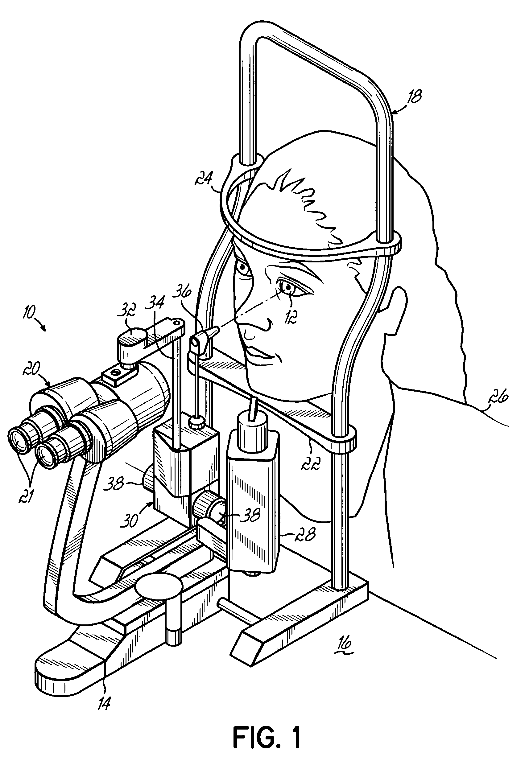
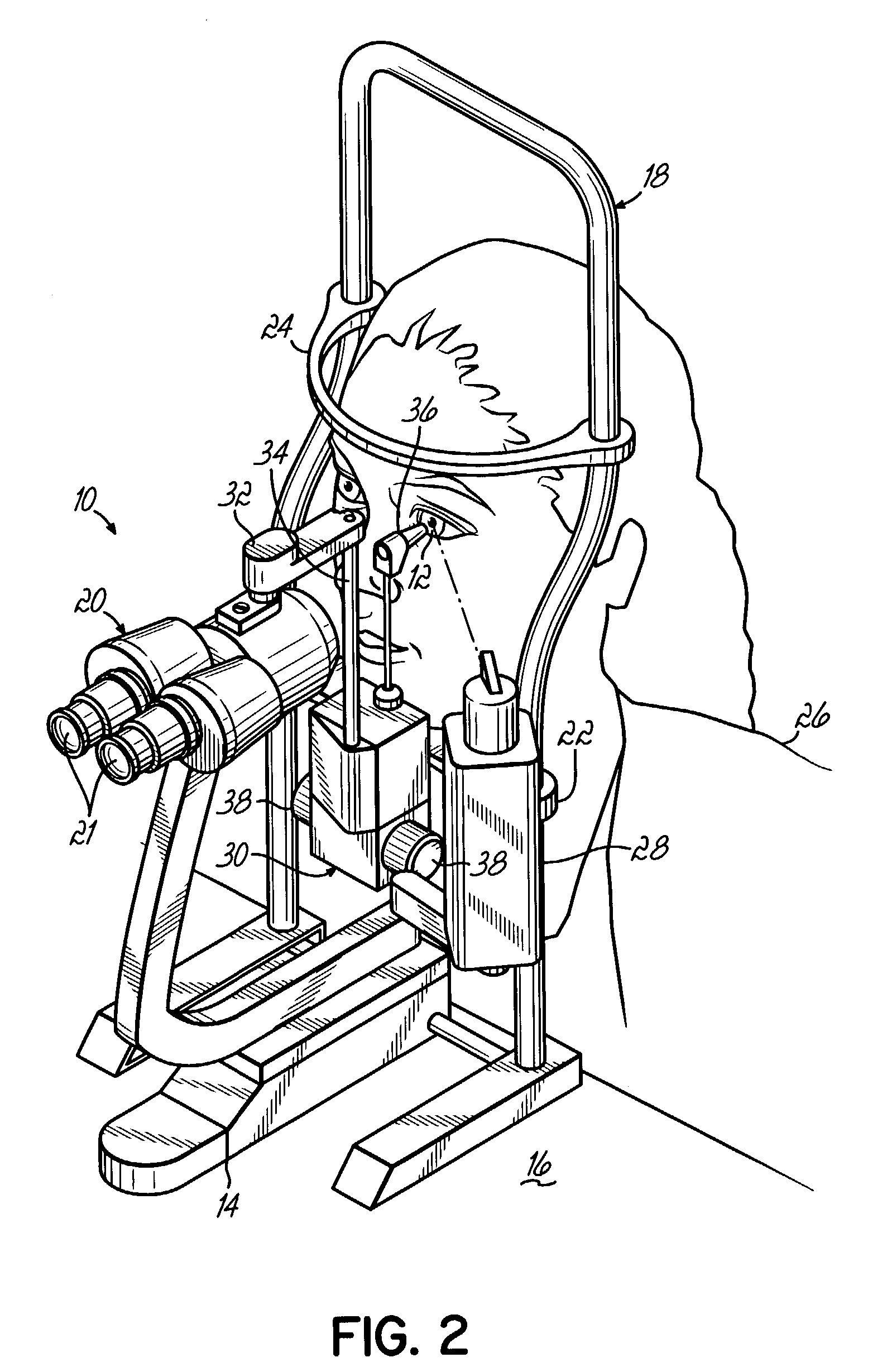
[0022]FIG. 1 shows a microscope assembly 10 configured to facilitate the examination of a patient's eye 12, as known in the art. The microscope assembly 10 generally comprises a base 14 which is securely mounted to a table 16, or other secure structure, and a patient support 18 extending upward from the base 14. A microscope 20 is pivotally supported to the base 14 and is shown in FIG. 1 as a biomicroscope, having dual eyepieces 21 for viewing the anatomy of a patient's eye 12. It will be recognized, however, that the microscope 20 may alternatively comprise only a single eyepiece. A chin rest 22 and a head brace 24 are coupled to the patient support 18, in a known manner, whereby a patient 26 may position his or her chin on the chin rest 22 and bring their head forward so that the forehead rests against the head brace 24 to position the patient 26 for observation through the microscope 20. The microscope assembly 10 further includes a slit lamp 28 pivotally mounted to the base 14, ...


PUM


Abstract

An improved applanation tonometer for measuring the intraocular pressure of an eye is configured for use with a conventional slit lamp. This applanation tonometer has a force sensor that senses the force applied by an applanation probe to flatten the cornea of the eye, while the cornea is viewed through the probe using the slit lamp. The force sensor generates a signal that corresponds to the applanation force and transmits the signal to a display and / or a data storage device.

Description

FIELD OF THE INVENTION[0001]The present invention pertains to medical diagnostic systems, and more particularly to an improved applanation tonometer with greater reliability in measuring the intraocular pressure of an eye.BACKGROUND OF THE INVENTION[0002]Tonometers are known in the art and are widely used to facilitate indirect measurement of the intraocular pressure of a person's eye. The ability to obtain measurements of intraocular pressure has proved important for detecting diseases, such as glaucoma, or other ailments of the eye.[0003]Various types of tonometers have been developed and may be classified, generally, as non-contact tonometers, indentation tonometers and applanation tonometers. Non-contact tonometers generally utilize a puff of air applied to the cornea of an eye in conjunction with shining a light beam onto the eye. As the cornea becomes flattened by the puff of air, the light intensity reflected from the cornea of the eye varies and is detected by an optical dev...

Claims


Application Information

Patent Timeline
IPC IPC(8): A61B3/16
CPCA61B3/16
Inventor DAVIDSON, JEFFERY C.
Owner J D MUELLER
Learn More