
Attachment structure of a load sensor for a vehicle seat

a technology for attaching structure and load sensor, which is applied in the direction of chairs, tractors, instruments, etc., can solve the problem that the importance of the attachment structure of the load sensor to the vehicle has not been recognized

Inactive Publication Date: 2006-01-03
AISIN SEIKI KK
View PDF17 Cites 47 Cited by
  • Summary
  • Abstract
  • Description
  • Claims
  • Application Information

AI Technical Summary

Benefits of technology

[0006]Accordingly, an object of this invention is to provide an attachment structure of a l

Problems solved by technology

However, in the known device, such importance of the attachment structure of the load sensor to the vehicle has not been recognized,

Method used


Image

  • Attachment structure of a load sensor for a vehicle seat
  • Attachment structure of a load sensor for a vehicle seat
  • Attachment structure of a load sensor for a vehicle seat

Examples


Embodiment Construction

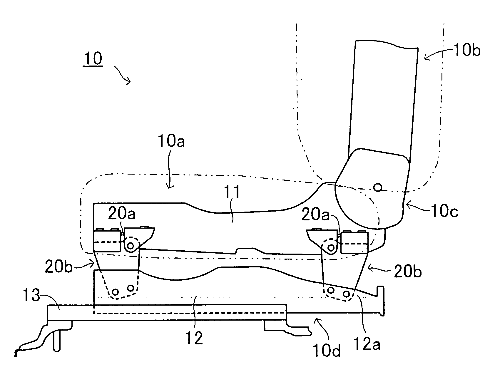
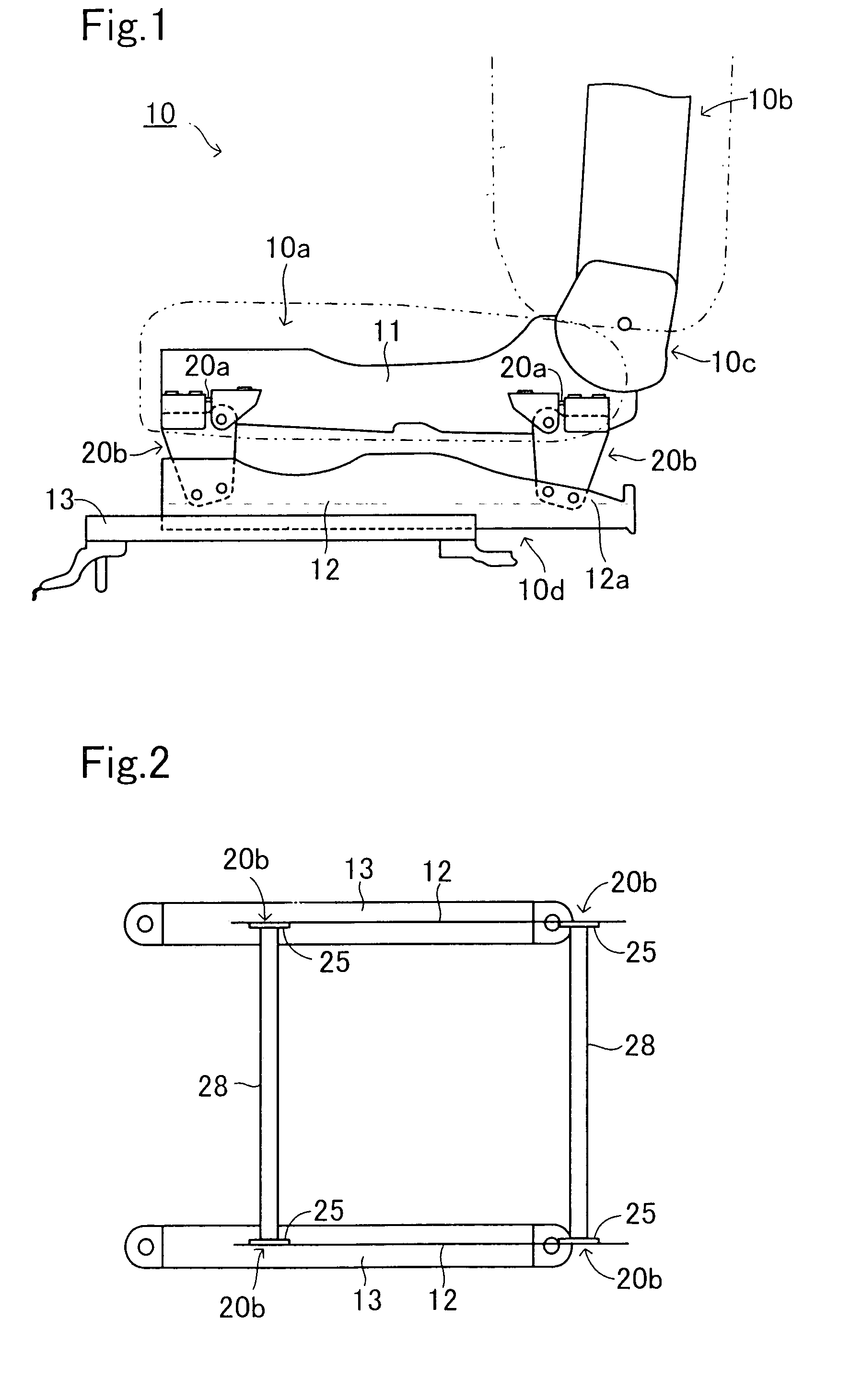
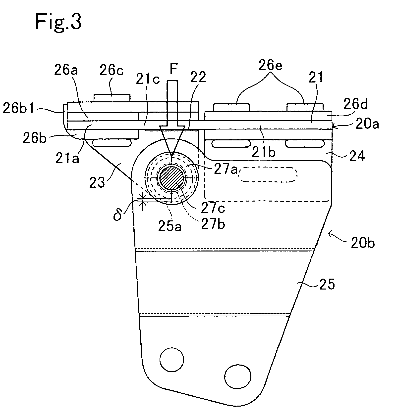
[0025]An embodiment of this invention will be explained with reference to the attached drawings. FIG. 1 shows a vehicle seat with a load sensor by applying an attachment structure according to one example of this invention. The vehicle seat 10 is comprised of a seat cushion 10a, a seat back 10b, a reclining mechanism 10c, a slide mechanism 10d, and an attachment structure unit 20b with a load sensor 20a installed between the seat cushion 10a, and the slide mechanism 10d.

[0026]In the vehicle seat 10, a lower end of the seat back 10b is installed in a rear end of the seat cushion 10a through the reclining mechanism 10c. The seat back 10b is held in a standing position by a function of the seat reclining mechanism 10c, and a reclining position of the seat back 10b in a longitudinal direction relative to the seat cushion 10a can be adjusted by operating the reclining mechanism 10c.

[0027]In the vehicle seat 10, a seat body is disposed on a floor of a vehicle body through the slide mech...


PUM


Abstract

An attachment structure for installing a load sensor to a vehicle seat includes the load sensor having a plate-shaped strain unit and a strain gauge for detecting a strain of the plate-shaped strain unit. The load sensor is structured that one end of the plate-shaped strain unit is fixed to a seating portion of the vehicle seat and the other end of the strain unit is fixed to a vehicle body. Also, a strain portion is defined between each fixed end of the plate-shaped strain unit, and the strain portion is deformable in a vertical direction relative to the vehicle seat. In addition, a load input point from the seating portion is defined approximately at a central portion of the strain portion of the plate-shaped strain unit.

Description

CROSS REFERENCE OF RELATED APPLICATION[0001]This application is based on and claims priority under 35 U.S.C. §119 with respect to Japanese Application No. 2001-278516 filed on Sep. 13, 2001, the entire content of which is incorporated herein by reference.FIELD OF THE INVENTION[0002]This invention relates to an attachment structure of a load sensor for a vehicle seat. More particularly, the present invention pertains to an attachment structure of a load sensor which detects a load on a seating portion of a seat when a passenger sits on the vehicle seat.BACKGROUND OF THE INVENTION[0003]In recent years, there is a tendency toward enforcing a safety of a passenger of a vehicle. In order to improve the safety of the passenger who sits on a seat, a restraint function of a seat belt and an operating function of an air bag in accordance with a weight of the passenger have been developed. When these devices are adopted, an accurate detection of a weight of the passenger is needed. As for one...

Claims


Application Information

Patent Timeline
IPC IPC(8): B60R21/16B60R21/00G01G3/14B60N2/00B60N2/015B60N2/90B60R21/01B60R21/015B60R22/46G01G19/12G01G19/52G01G23/02
CPCB60N2/002B60R21/0152B60R21/01516B60N2/015
Inventor SAKAMOTO, KAZUNORISUZUKI, YASUAKITAKEUCHI, TSUTOMUSAKAI, MORIOHASEGAWA, YASUNORIMORISHITA, KENTARO
Owner AISIN SEIKI KK
Learn More