
Tailored blank

a blank and tailored technology, applied in the field of tailoring blanks, can solve the problems of increasing manufacturing complexity and complex finished products

Inactive Publication Date: 2005-12-20
DULEY WALTER +5
View PDF35 Cites 41 Cited by
  • Summary
  • Abstract
  • Description
  • Claims
  • Application Information

AI Technical Summary

Benefits of technology

"The present invention provides a method of making a component from a tailored blank with two parts. The first part has an aperture, and the second part has an embossment that fits the aperture and a surrounding flange that overlaps the first part. The two parts are positioned face to face and secured together to form a planar blank. The embossment is nested in the aperture, resulting in a flush surface between the first part and the embossment. The blank is then deformed to create the final component. This method allows for the creation of components with precise fit and surface quality."

Problems solved by technology

The need to use multiple components may result from the complexity of the finished product or may result from the different characteristics of the material required in different areas of the component.
The use of multiple elements to produce the finished component increases the manufacturing complexity.

Method used


Image

  • Tailored blank
  • Tailored blank
  • Tailored blank

Examples


Embodiment Construction

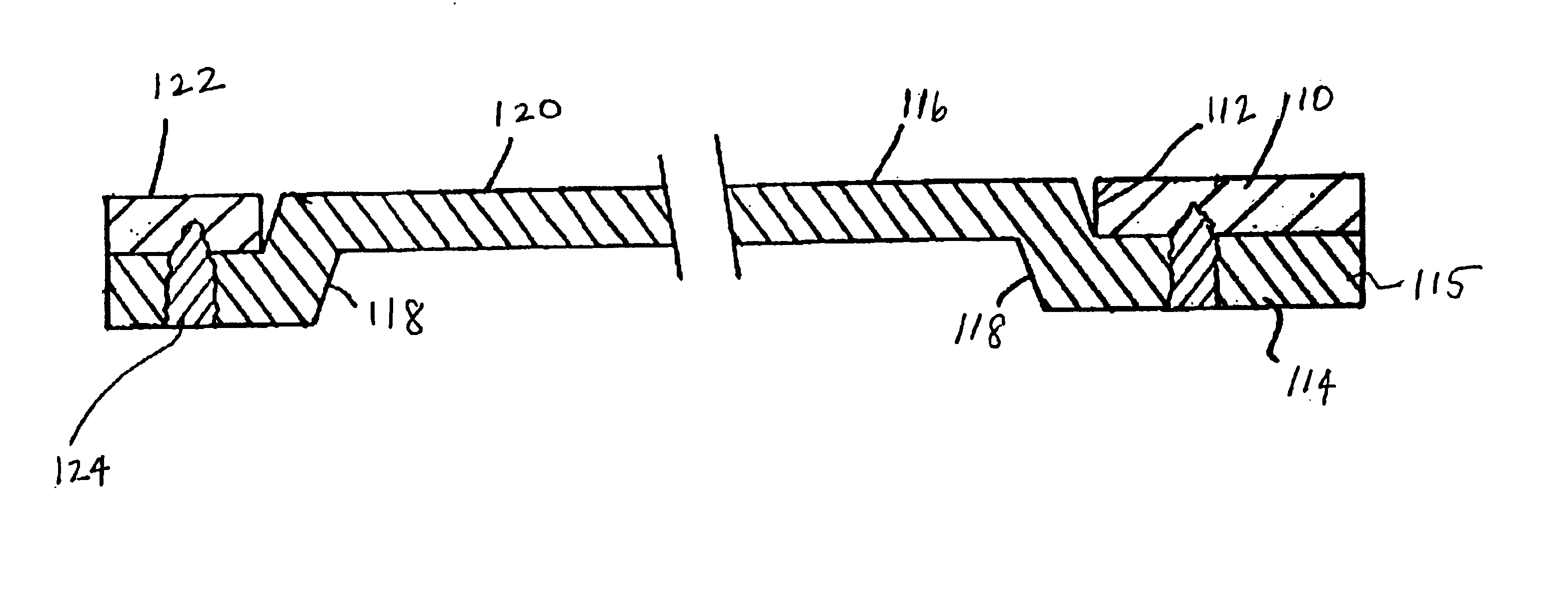
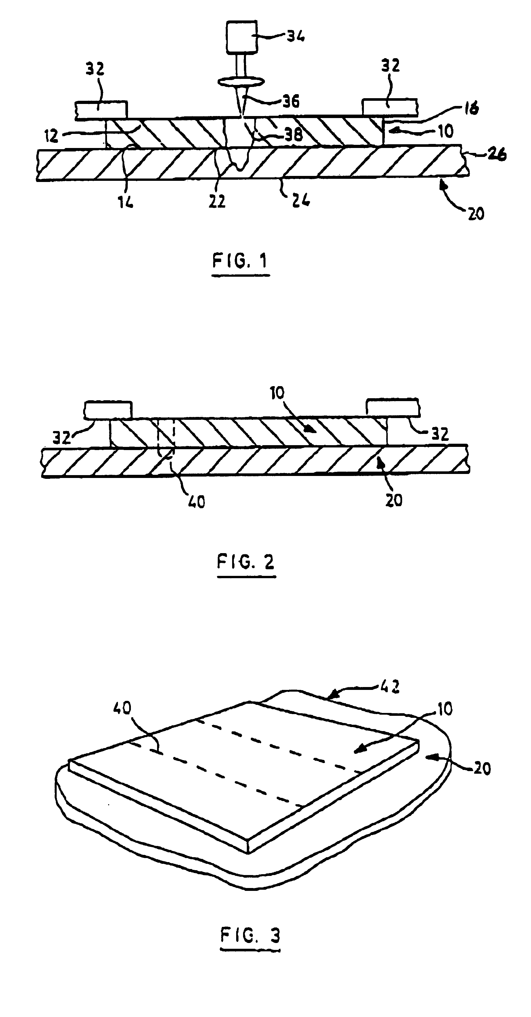
[0032]Referring therefore to FIG. 1, a pair of constituent parts 10, 20 which may have differing characteristics—in this case differing thicknesses—are each planar and formed from weldable sheet metal. As such, each has a pair of oppositely directed major surfaces 12, 14 and 22, 24 interconnected at the periphery by edges 16, 26 respectively.

[0033]The constituent parts 10, 20 are positioned in juxtaposition with one major surface 14 of the constituent part 10 overlying and in abutment with one of the major surfaces 22 of the constituent part 20. The constituent part 10, which is of smaller area than that of the constituent part 20, is positioned within the periphery of part 20 such that after forming, an increased thickness of material will be available in the desired region of the finished component.

[0034]The constituent parts 10, 20 are secured in abutting relationship by clamps 32 of suitable form including magnetic clamps if the components themselves are magnetic. A laser 34 dir...


PUM

PropertyMeasurementUnit
thickaaaaaaaaaa
thicknessaaaaaaaaaa
shapesaaaaaaaaaa

Abstract

The present invention provides a tailored blank having a pair of sheet metal constituent parts each having a pair of oppositely directed major surfaces. The first constituent part has an aperture while the second constituent part has an embossment to fit the aperture. The first and second constituent parts are then secured to one another to form the tailored blank. The blank may then be subsequently formed into a component of varying material characteristics.

Description

[0001]This application is a Continuation-In-Part of U.S. Ser. No. 09 / 694,889 filed on Oct. 25, 2000 now abandoned and U.S. Ser. No. 09 / 341,575 filed on Oct. 1, 1999, now U.S. Pat. No. 6,426,153 which is a 371 of PCT / CA97 / 00854 filed on Nov. 13, 1997 the contents of which are incorporated herein by reference.FIELD OF THE INVENTION[0002]The present invention relates to a method of forming tailored blanks to be used to produce shaped metal components.BACKGROUND OF THE PRIOR ART[0003]Sheet metal components of complex shapes are typically produced from a planar blank that is formed into the finished shape through a series of forming or stamping operations. Where relatively complex components are to be produced, it is usual to build the component out of a number of individual elements, each of which is stamped from a blank. The need to use multiple components may result from the complexity of the finished product or may result from the different characteristics of the material required in...

Claims


Application Information

Patent Timeline
Patent Type & Authority Patents(United States)
IPC IPC(8): B21D22/00B23K26/20B23K26/24
CPCB21D22/00B23K26/20B23K26/246B23K2201/185Y10T428/12243Y10T428/12264Y10T428/12361Y10T428/12486Y10T428/12229Y10T428/12347B23K26/244B23K26/26B23K26/242B23K26/282B23K2101/185
Inventor DULEY, WALTEROGMEN, MELIHHUGHES, DAVIDBLACK, GARY KEITHMORRIS, BRIANSTAPLES, MICHAEL JAMES
Owner DULEY WALTER
Learn More