
Mounting assembly for a vehicle suspension arm

a technology for suspension arms and mounting parts, applied in the field of large vehicles, can solve the problems of extreme specifications of emergency vehicles, and achieve the effect of easy replacemen

Inactive Publication Date: 2005-12-20
OSHKOSH CORPORATION
View PDF28 Cites 128 Cited by
  • Summary
  • Abstract
  • Description
  • Claims
  • Application Information

AI Technical Summary

Benefits of technology

The solution enhances stability by lowering the vehicle's center of gravity and improves visibility while facilitating easier maintenance and component replacement, addressing the complexities of mounting heavy components in demanding environments.

Problems solved by technology

Military and other emergency vehicles must be designed to extremely demanding specifications.

Method used


Image

  • Mounting assembly for a vehicle suspension arm
  • Mounting assembly for a vehicle suspension arm
  • Mounting assembly for a vehicle suspension arm

Examples


Embodiment Construction

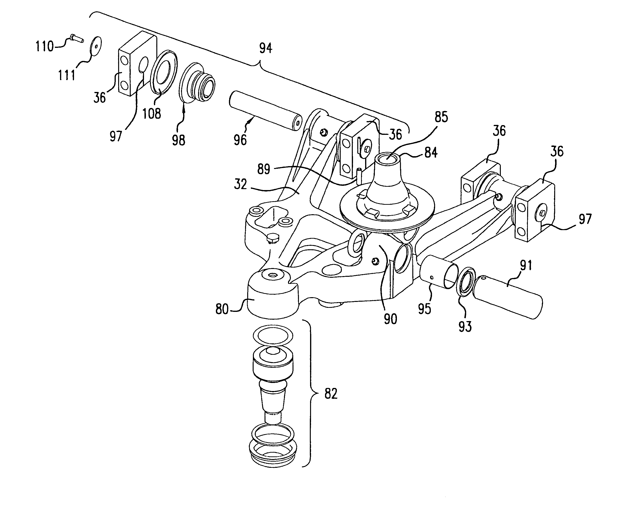
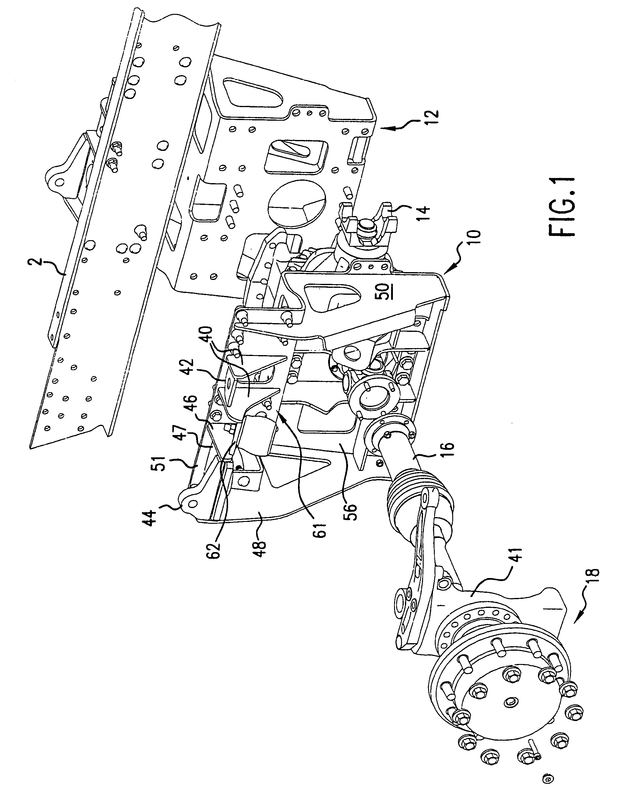
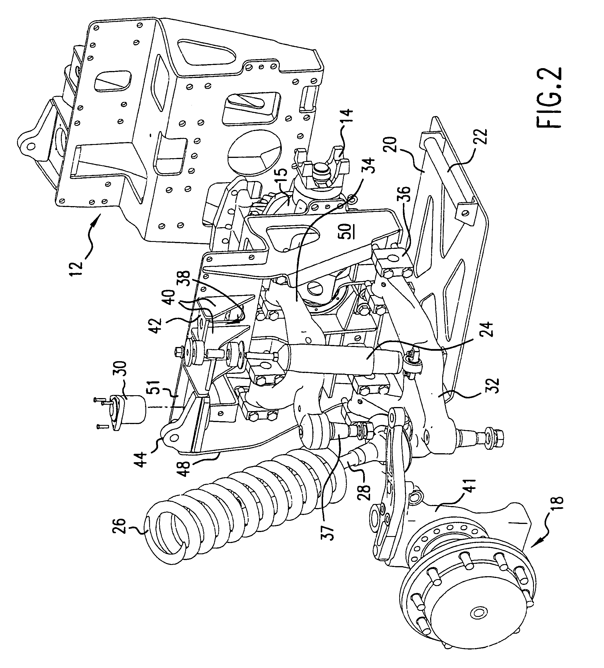
[0023]FIG. 1 shows the front portion of a vehicle and its suspension support in relation to a frame rail 2 of a vehicle. A left-hand or first side plate 10 is mounted beneath a left-hand frame rail (not shown), and a right-hand or second side plate 12 is mounted beneath a right-hand frame rail 2. Several bolts are used to connect each of the side plates 10 and 12 to its respective frame rail. A differential 15 with a differential drive connection 14 is connected to each of the side plates 10 and 12. As further shown in FIGS. 2 and 3, it is clear that the main side plates 10 and 12 are joined together by the lower plate 20, bar 22 and differential 15 at the lower portions of the side plates 10 and 12. The side plates shown in FIGS. 1 through 6 are for a suspension which is not equipped with an anti-sway bar.

[0024]Referring now to the first plate 10 shown in FIGS. 1 through 6, it is comprised of three main components which are welded together. Those components are: a longitudinally ex...


PUM


Abstract

A mounting assembly for use with a mounting surface includes an arm, a pin, a pair of clamping blocks and a fastener. The arm has a cylindrical bore at one end. The pin extends through the bore. Each block of the pair of clamping blocks includes a central opening and is circumferentially discontinuous about the central opening. Each clamping block further includes a slot defined by portions of the block. The slot is dimensioned to allow the pin to pass through the slot when the block is in an unclamped position and to tightly grip the pin when the block is in a clamped position. The fasteners extend across the slots and are configured to engage the mounting surface to mount the blocks to the mounting surface.

Description

CROSS-REFERENCE TO RELATED PATENT APPLICATIONS[0001]This application is a continuation application of U.S. application Ser. No. 09 / 635,579, now U.S. Pat. No. 6,764,085, from which priority is claimed under 35 U.S.C. §120. The full disclosure, in its entirety, of U.S. application Ser. No. 09 / 635,579 is hereby incorporated by reference.BACKGROUND[0002]The present invention relates to large vehicles having independent suspensions, such as those which are typically used in military applications and in large municipal vehicles, such as fire trucks. In particular, the invention relates to a frame and independent suspension assembly which allows a vehicle to have better stability by lowering the center of gravity, and better visibility because of the lower drivetrain and lower hoodline.[0003]Military and other emergency vehicles must be designed to extremely demanding specifications. The vehicles must be capable of driving over or through obstacles which only a tactical or emergency driver...

Claims


Application Information

Patent Timeline
Patent Type & Authority Patents(United States)
IPC IPC(8): B60G7/00B60G7/04B60G11/16B60G21/055B62D21/11
CPCB60G7/00B60G11/16B60G21/0551B62D21/11B60G7/04Y10T403/32893B60G2200/144B60G2200/422B60G2200/44B60G2202/12B60G2202/135B60G2204/1224B60G2204/124B60G2204/143B60G2204/148B60G2204/41B60G2204/416B60G2204/4502B60G2206/0114B60G2206/50B60G2206/601B60G2206/91B60G2300/02B60G2300/14B60G2300/38Y10T403/32901
Inventor ARCHER, DAVID W.ANDERSON, BRIAN K.
Owner OSHKOSH CORPORATION
Learn More