
Method, system, and program for reducing toner usage in print output

a technology of toner usage and print output, applied in the direction of digital output to print units, visual presentation using printers, instruments, etc., can solve the problems of increasing the manufacturing cost of printers, substantially increasing electromagnetic radiation (emi), and inability to reduce toner usage in all black areas, so as to reduce toner usage, reduce emi radiation, and reduce the effect of toner usag

Inactive Publication Date: 2005-12-13
RICOH KK
View PDF30 Cites 43 Cited by
  • Summary
  • Abstract
  • Description
  • Claims
  • Application Information

AI Technical Summary

Benefits of technology

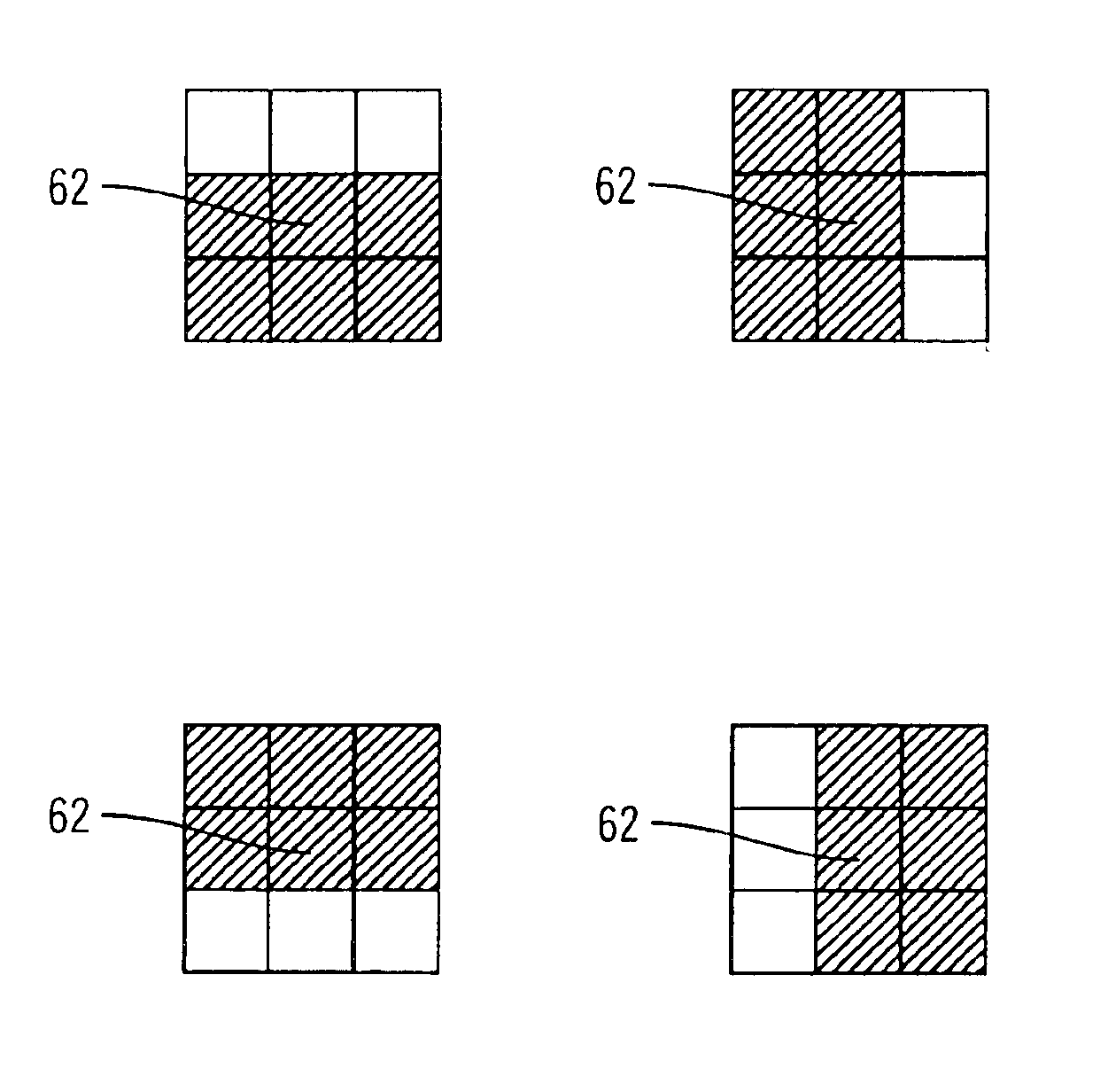
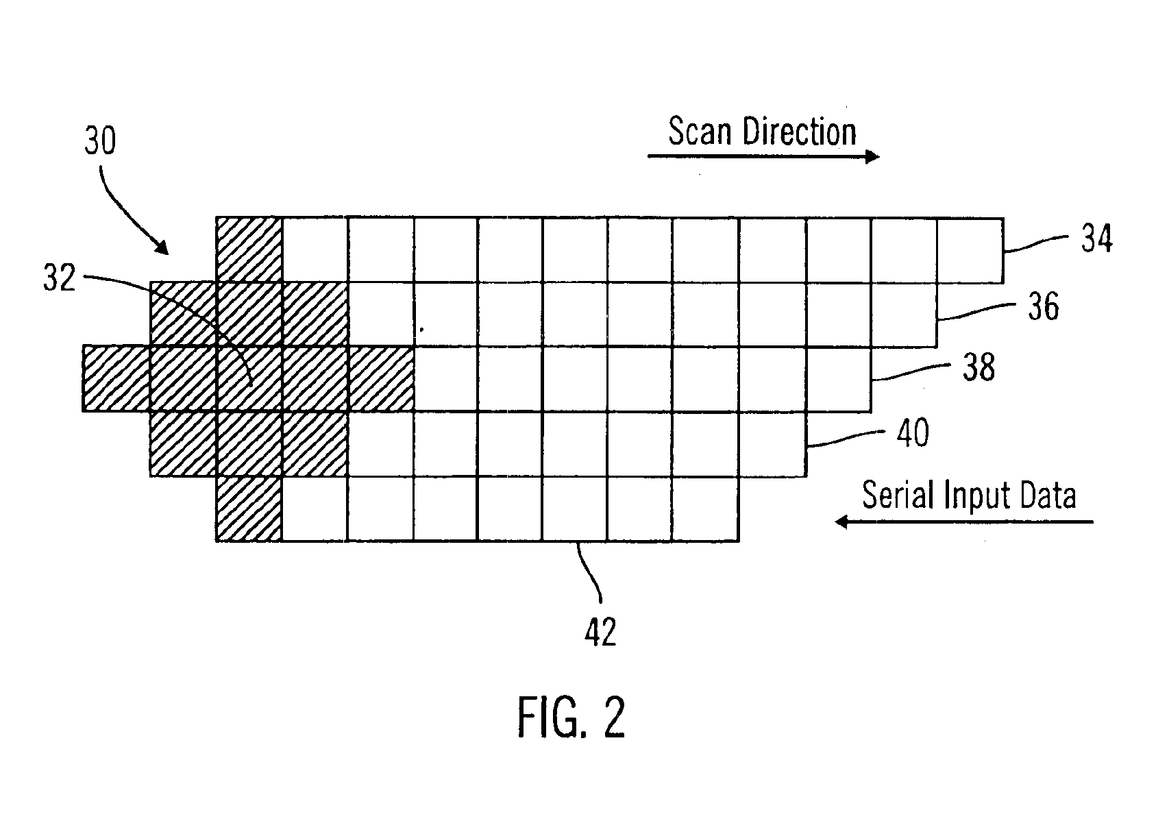
[0015]Preferred embodiments provide a technique for sub-pulse width modulation to reduce toner usage that minimizes EMI radiation by using position information to align sub-pel regions formed by the sub-pulse width modulations in adjacent pels next to each other so the laser beam does not have to turn on and off within every pel when generating the sub-pel regions in the black filled region. The preferred embodiment technique minimizes the number of times the laser beam must turn on and off to form sub-pel regions in pels in a black filled region to reduce toner usage. Further, with preferred embodiments, pels on an image edge are preserved and not eliminated as part of the toner reduction algorithm. This preserves image quality and avoids producing a “washed-out” appearance of the image by avoiding removal of edge pels that define the outline of an image.

Problems solved by technology

This process of switching the laser on and off substantially increases electromagnetic radiation (EMI).
The addition of these electromagnetic patches or other fixes to avoid the EMI radiation pollution significantly increases the manufacturing cost of the printer to a point where the use of sub-pulse width modulation to reduce toner usage in all black areas is not feasible.
The problem with this approach is that because data is removed without any consideration to the image structure, it is possible that the algorithm would delete significant portions of the image, such as edge pels that form the outline of the image.
This reduces the edge resolution and quality of the image resulting in a “washed-out” appearance.

Method used


Image

  • Method, system, and program for reducing toner usage in print output
  • Method, system, and program for reducing toner usage in print output
  • Method, system, and program for reducing toner usage in print output

Examples


Embodiment Construction

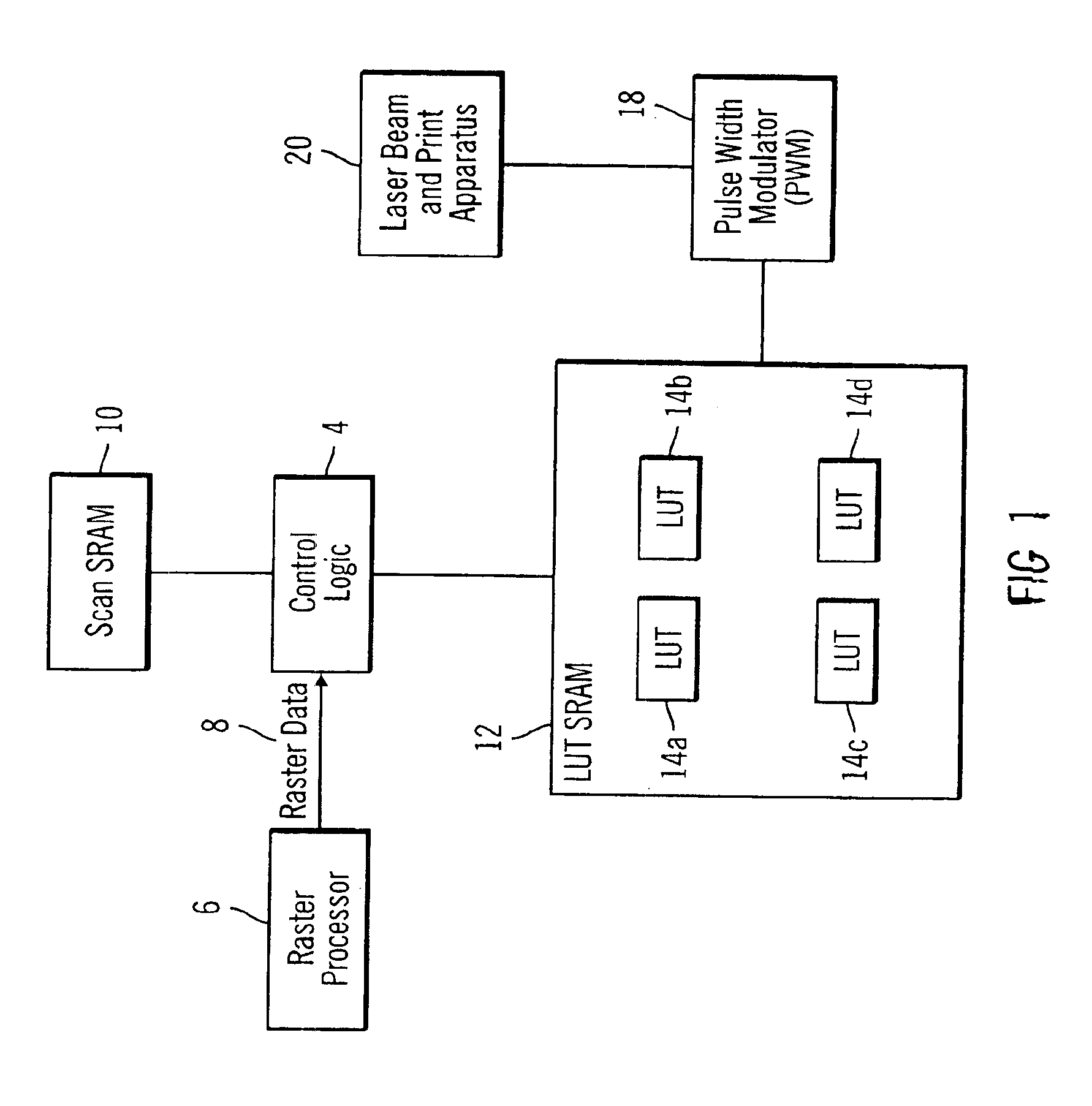
[0012]To overcome the limitations in the prior art described above, preferred embodiments disclose a method, system, and program for reducing toner in an image comprised of raster pel data. A determination is made of pels surrounding subject pels. For each subject pel, a sub-pulse width power is generated to charge a sub-pel region within the subject pel based on a pattern of the surrounding pels of the subject pel. Further, for each subject pel, position information is generated indicating an alignment of the sub-pel region in the pel. The position information is used to position the sub-pel region produced by the sub-pulse width power in the pel.

[0013]Still further, for each subject pel, a determination is made as to whether the pattern of the surrounding pels indicate that the subject pel is in a black filled region. The position information is used to align the sub-pel regions in the subject pels in the black filled region to be adjacent to the sub-pel region in one adjacent sub...


PUM


Abstract

Disclosed is a method, system, and program for reducing toner in an image comprised of raster pel data. A determination is made of pels surrounding subject pels. For each subject pel, a sub-pulse width power is generated to charge a sub-pel region within the subject pel based on a pattern of the surrounding pels of the subject pel. Further, for each subject pel, position information is generated indicating an alignment of the sub-pel region in the pel. The position information is used to position the sub-pel region produced by the sub-pulse width power in the pel.

Description

CROSS-REFERENCE TO RELATED APPLICATIONS[0001]This application is related to the following co-pending and commonly-assigned patent applications, all of which are filed on the same date herewith, and all of which are incorporated herein by reference in their entirety:[0002]“Method, System, And Program For Using Look-up Tables to Filter Raster Data”, by Richard S. Lucky, Larry M. Ernst, and Danielle K. Dittrich; and[0003]“Method, System, And Program For Producing a Look-up Table to Enhance Print Quality”, by Danielle K. Dittrich, Larry M. Ernst, and Richard S. Lucky.BACKGROUND OF THE INVENTION[0004]1. Field of the Invention[0005]The present invention relates to a method, system and program for reducing toner usage in print output.[0006]2. Description of the Related Art[0007]To print an image, a print engine processor, referred to herein as a raster image processor, converts the image in a page description language or vector graphics format to a bit mapped image indicating a value to pr...

Claims


Application Information

Patent Timeline
IPC IPC(8): G06K15/00G06F3/12G06K15/12
CPCG06K15/1223G06K15/128G06F3/12
Inventor ERNST, LARRY M.DITTRICH, DANIELLE KATHYRNLUCKY, RICHARD S.
Owner RICOH KK
Learn More