Perimetric detection system

a detection system and perimetric technology, applied in the field of perimetric detection systems, can solve the problems of inconvenient use, easy false alarms from passing objects or persons, inconvenient or bothersome use, etc., and achieve the effects of minimizing system complexity and volume of space required for operation, avoiding the effect of affecting the accuracy of detection results, and reducing the complexity of the system

Inactive Publication Date: 2005-12-13
BRENT MARK R
View PDF60 Cites 70 Cited by
  • Summary
  • Abstract
  • Description
  • Claims
  • Application Information

AI Technical Summary

Benefits of technology

[0015]The current invention describes a system for creating a continuous, collimated detection zone for an automatically-actuated device or container, such as an automatic waste container, wherein the detection zone can be made to match the opening periphery of the container, is height adjustable, immune from ambient light fluctuations and relatively simple and inexpensive to produce. Though numerous types and arrangements of automatic doors may be used, one configuration is described herein that utilizes flexible, sliding doors that minimize system complexity and volume of space required for operation.
[0025]The ring is a relatively inexpensive, unitary, molded plastic part that contains all lens elements and emitting surfaces in fixed orientations relative to each other, thereby obviating the need for multiple, precision optical components and / or individual adjustment of the optics to create a continuous, uniform light curtain surrounding the prescribed area.
[0026]A fourth embodiment of the ring adapts the concepts described in the previous embodiments to define a detection zone that only partially circumscribes an enclosed area. In some applications, waste containers may be partially recessed into walls or situated with one side flush against a wall, so that only a portion of the container rim protrudes beyond the wall surface. These configurations only require a detection zone that extends from that portion of the rim that is exposed beyond the wall surface—i.e., the physical barrier of the contiguous wall obligates all incoming objects to pass over the exposed rim before gaining access to the container opening. Furthermore, the adjoining wall structure might be configured such that it would interfere with the detection zone if the zone were to completely circumscribe the container opening. Reflections of emitted radiation from the wall may make it difficult to achieve optimum detection sensitivity while simultaneously avoiding false triggerings.
[0029]In order to facilitate the tossing of refuse into the container, the doors may be driven at high speed, so they open before incoming objects would otherwise make contact. To minimize the power draw of the motors during high accelerations, elastic spring elements can be utilized to provide additional motive energy. The spring elements are deformed to store energy during the door-closing phase, when the doors are driven at slower speeds and power draw of the motors is lower. One or more controllable clutches are required to restrain the spring elements and prevent the dissipation of stored energy prematurely.

Problems solved by technology

Various waste containers with hand-operated lids have been developed, but suffer from inconvenience in use and risk of contamination when touched.
Foot-operated designs minimize contamination risk, but are also often inconvenient or bothersome to use.
Users of both hand and foot operated waste containers may be occupied with multiple tasks, or be situated in an inconvenient position, and not have a free hand or foot to operate the container lid.
This type of automatic can is readily prone to false alarms from passing objects or persons.
Additionally, the requirement for an inner bay compromises the automatic waste container's ability to contain contaminating objects and noxious emissions to the can's shielded interior.
It is difficult to avoid this condition when a shielded photoelectric detection zone is created in front of an opening.
For the user to pause while the door opens is inconvenient, so the comfortable zone offset distance is significant.
This curtails false triggerings, as well as variations in detector sensitivity caused by fluctuations in ambient lighting conditions.
However, known light curtain technology has several drawbacks when considered for this application.
Additionally, the cost and complexity of combining multiple light curtains created by prior art technology to enclose a defined area is prohibitive when considered for the current goal of creating an inexpensive, automatic waste container.

Method used


Image

  • Perimetric detection system
  • Perimetric detection system
  • Perimetric detection system

Examples


Embodiment Construction

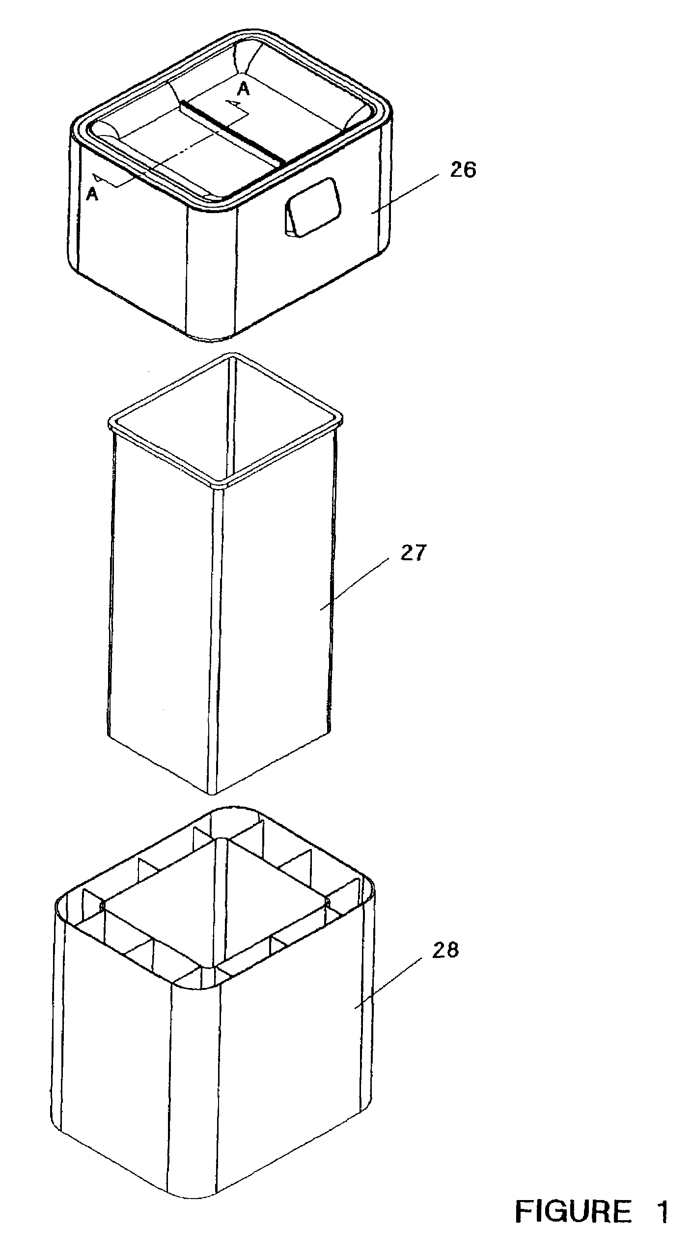
[0066]FIG. 1 shows an exploded view of one embodiment of an automatic waste container utilizing the detection system of the present invention. A receptacle 27 for containing discarded refuse is fitted to a support base 28. The housing module 26 is placed over the rim of the receptacle 27, thereby covering the opening of the receptacle 27. The housing module 26 covers a substantial portion of the upper sidewalls of the receptacle 27, and so also serves to cover the exposed upper portions of a disposable plastic bag, of the type that may be used to line waste container interiors.

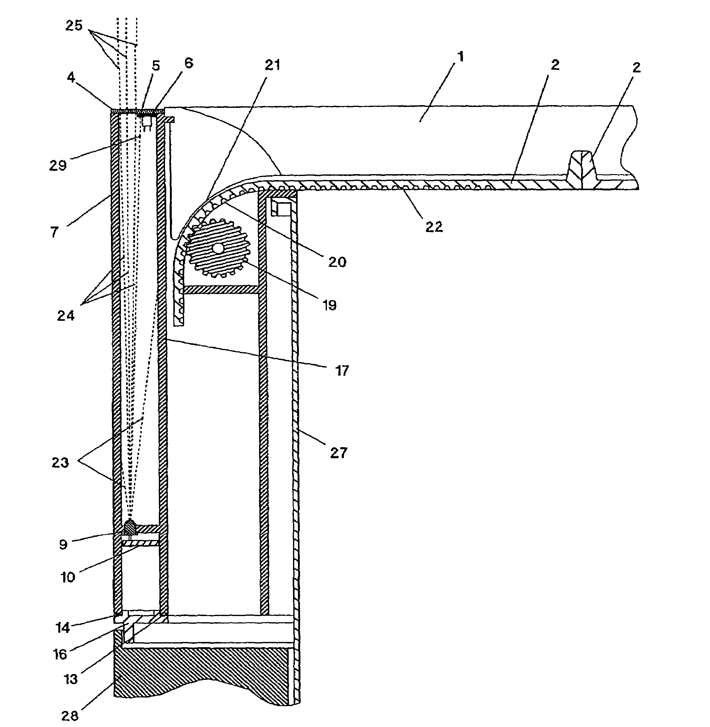
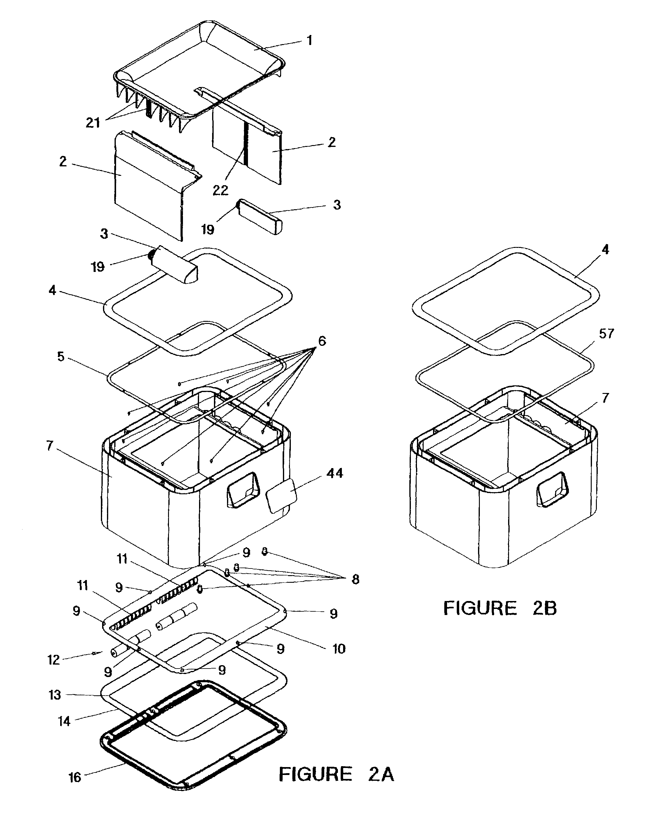
[0067]FIG. 2A shows an exploded view of the housing module 26. The main structural component is the housing 7. The housing 7 is a plastic, injection-molded part, as are the other structural components, bezel 1 and bottom cover 16. The walls and ribs of the housing 7 create multiple interior spaces. Eight of the interior spaces circumvent the opening of the housing 7, which is situated directly above the openin...


PUM


Abstract

Systems and elements are disclosed for creating a continuous, collimated detection zone for an automatically-actuated device or container, such as an automatic waste container, wherein the detection zone can be made to match the periphery of a defined area, such as the opening periphery of the container, is height adjustable and immune from ambient light fluctuations.

Description

REFERENCE TO RELATED APPLICATIONS[0001]This application for U.S. patent is a continuation-in-part of U.S. patent application Ser. No. 09 / 865,795 filed May 25, 2001, now U.S. Pat. No. 6,596,983, which claims the priority of U.S. provisional application for patent Ser. No. 60 / 207,676 filed May 26, 2000, the disclosure of which is incorporated by reference herein in its entirety.FIELD OF THE INVENTION[0002]The present invention relates generally to systems for detecting objects, and, more particularly, relates to photodetector systems and automatically actuated devices utilizing such systems.BACKGROUND OF THE INVENTION[0003]It is desirable to have lids on waste containers to contain unpleasant sights and odors, and to protect against contamination from objects therein. Various waste containers with hand-operated lids have been developed, but suffer from inconvenience in use and risk of contamination when touched. Foot-operated designs minimize contamination risk, but are also often inc...

Claims


Application Information

Patent Timeline
IPC IPC(8): B65F1/16G01V8/20
CPCB65F1/1638G01V8/20B65F2210/168
Inventor BRENT, MARK R.
Owner BRENT MARK R
Why Eureka
Try Eureka