
System and method for blocking and/or retaining a prosthetic spinal implant

a prosthetic and spinal implant technology, applied in the field of spinal implants, can solve the problems of numbness, muscle weakness and paralysis, intervertebral disc deterioration, and displaced or damaged intervertebral discs,

Inactive Publication Date: 2005-12-13
WARSAW ORTHOPEDIC INC
View PDF76 Cites 324 Cited by
  • Summary
  • Abstract
  • Description
  • Claims
  • Application Information

AI Technical Summary

Benefits of technology

These solutions effectively anchor and block spinal implants, reducing migration and expulsion, thereby stabilizing the spine and alleviating pain by maintaining the disc space and promoting fusion of adjacent vertebrae.

Problems solved by technology

Intervertebral discs may be displaced or damaged due to trauma or disease.
The extruded nucleus pulposus may press on the spinal nerve, which may result in nerve damage, pain, numbness, muscle weakness and paralysis.
Intervertebral discs may also deteriorate due to the normal aging process.
As a disc dehydrates and hardens, the disc space height will be reduced, leading to instability of the spine, decreased mobility and pain.
The removal of the damaged or unhealthy disc may allow the disc space to collapse, which could lead to instability of the spine, abnormal joint mechanics, nerve damage, as well as severe pain.
Even though a certain degree of success with these devices has been achieved, full motion is typically never regained after such intervertebral fusions.
Many of these devices are complicated, bulky and made of a combination of metallic and elastomeric components and thus never fully return the full range of motion desired.
However, once positioned in the disc space, many hydrogel implants may migrate in the disc space and / or may be expelled from the disc space through an annular defect.
Closure of the annular defect, or other opening, using surgical sutures or staples following implantation is typically difficult and, in some cases, ineffective.

Method used


Image

  • System and method for blocking and/or retaining a prosthetic spinal implant
  • System and method for blocking and/or retaining a prosthetic spinal implant
  • System and method for blocking and/or retaining a prosthetic spinal implant

Examples


Embodiment Construction

[0059]For the purposes of promoting an understanding of the principles of the invention, reference will now be made to certain preferred embodiments and specific language will be used to describe the same. It will nevertheless be understood that no limitation of the scope of the invention is thereby intended. All embodiments of the present invention, including those explicitly disclosed, those inherently disclosed, and those that would normally occur to persons skilled in the art, are desired to be protected.

[0060]The present invention relates to prosthetic spinal implants that are blocked and / or anchored to prevent excessive migration in and / or expulsion from the disc space. Methods of using such implants are also disclosed. The spinal implants described herein include those that may be useful as nucleus pulposus replacements, partial or complete disc replacements, and those that may be useful in other disc reconstruction or augmentation procedures.

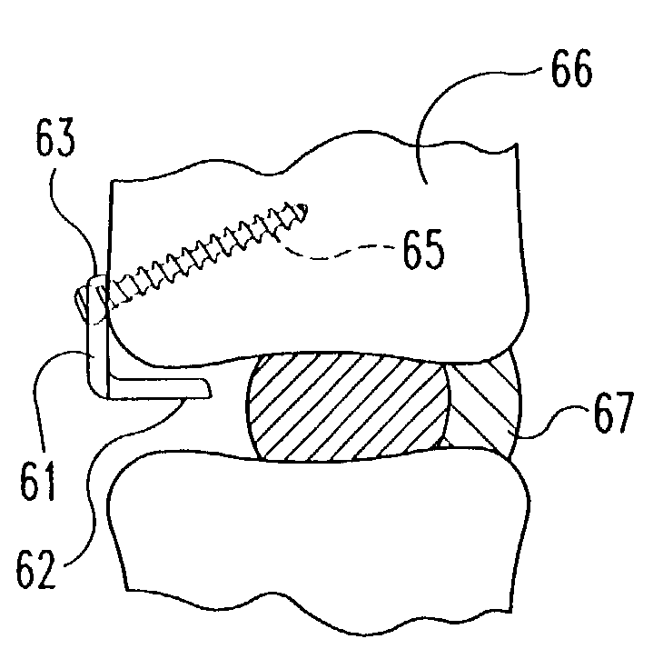
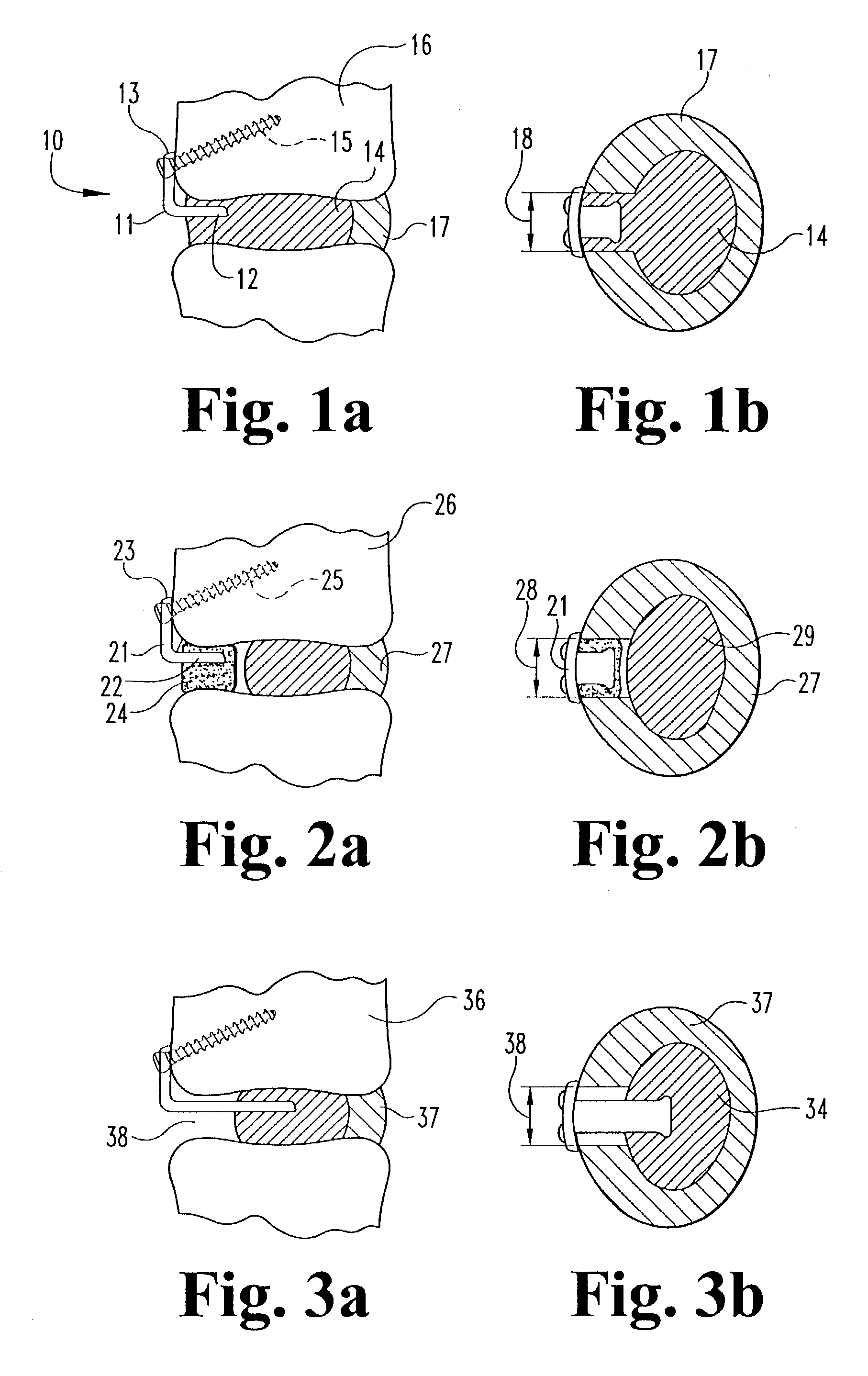
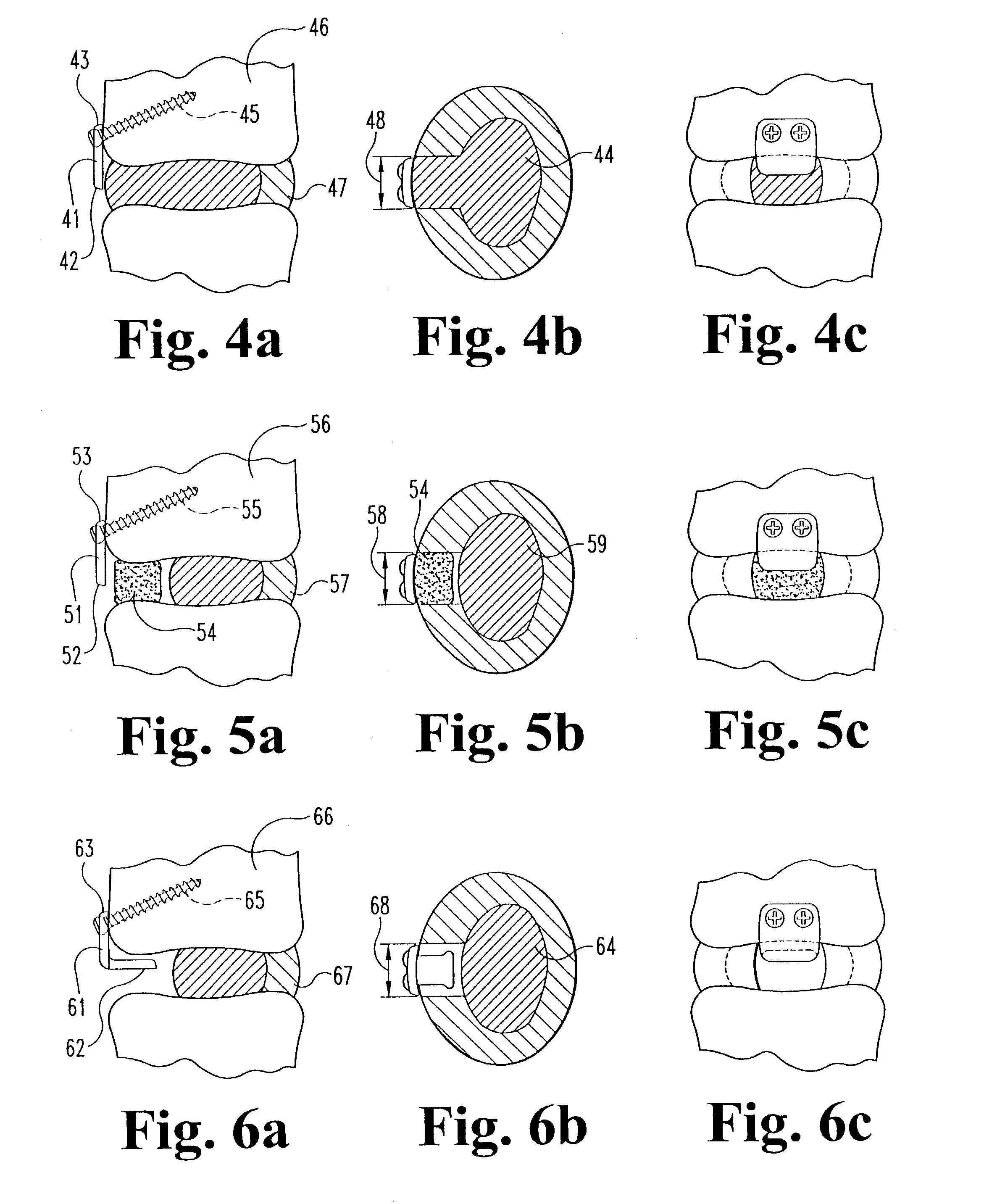
[0061]Referring now to the drawin...


PUM

PropertyMeasurementUnit
compressive strengthsaaaaaaaaaa
flexibleaaaaaaaaaa

Abstract

Devices for anchoring and / or blocking spinal implants in an intervertebral disc space are disclosed. In one aspect of the invention the device includes a rigid blocking member having one end unconnected and free to block a spinal implant, and another end attached to a securing member to secure the blocking member to the spine. Methods for using the inventive anchoring / blocking implants are also provided.

Description

[0001]This application claims the benefit of Provisional Application No. 60 / 432,368, filed Dec. 10, 2002.FIELD OF THE INVENTION[0002]The present invention relates generally to spinal implants, and more particularly to devices for blocking and / or retaining implants in an intervertebral disc space.BACKGROUND OF THE INVENTION[0003]The intervertebral disc functions to stabilize the spine and to distribute forces between vertebral bodies. A normal disc includes a gelatinous nucleus pulposus, an annulus fibrosis and two vertebral end plates. The nucleus pulposus is surrounded and confined by the annulus fibrosis.[0004]Intervertebral discs may be displaced or damaged due to trauma or disease. Disruption of the annulus fibrosis allows the nucleus pulposus to protrude into the spinal canal, a condition commonly referred to as a herniated or ruptured disc. The extruded nucleus pulposus may press on the spinal nerve, which may result in nerve damage, pain, numbness, muscle weakness and paralys...

Claims


Application Information

Patent Timeline
Patent Type & Authority Patents(United States)
IPC IPC(8): A61B17/70A61F2/00A61F2/02A61F2/28A61F2/30A61F2/44
CPCA61B17/70A61F2/442A61B17/7059A61F2/28A61F2/30965A61F2002/30062A61F2002/30092A61F2002/30578A61F2002/4435A61F2002/444A61F2002/445A61F2210/0004A61F2210/0014A61F2310/00017A61F2310/00023A61F2310/00095A61F2310/00125A61F2310/00131A61F2310/00137A61F2310/00167A61F2310/00179A61F2310/00203A61F2310/00239A61F2310/00329A61F2310/00365Y10S606/907Y10S606/91Y10S606/911A61F2310/00359
Inventor TRIEU, HAI H.
Owner WARSAW ORTHOPEDIC INC
Learn More