
Safety drive hammer for a dynamic cone penetrometer

Inactive Publication Date: 2005-12-13
SAWYERS J MICHAEL
View PDF11 Cites 17 Cited by
  • Summary
  • Abstract
  • Description
  • Claims
  • Application Information

AI Technical Summary

Benefits of technology

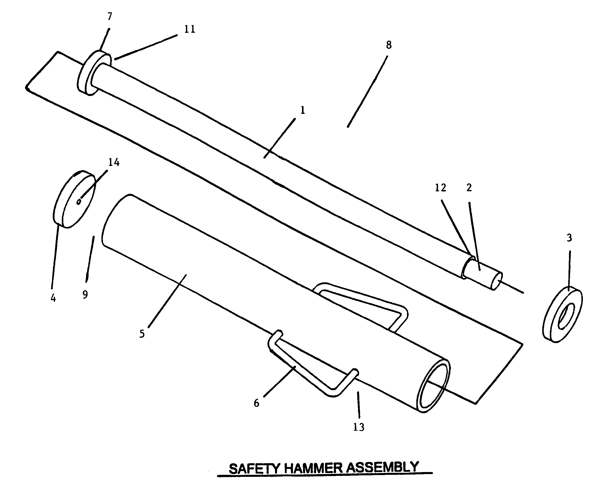
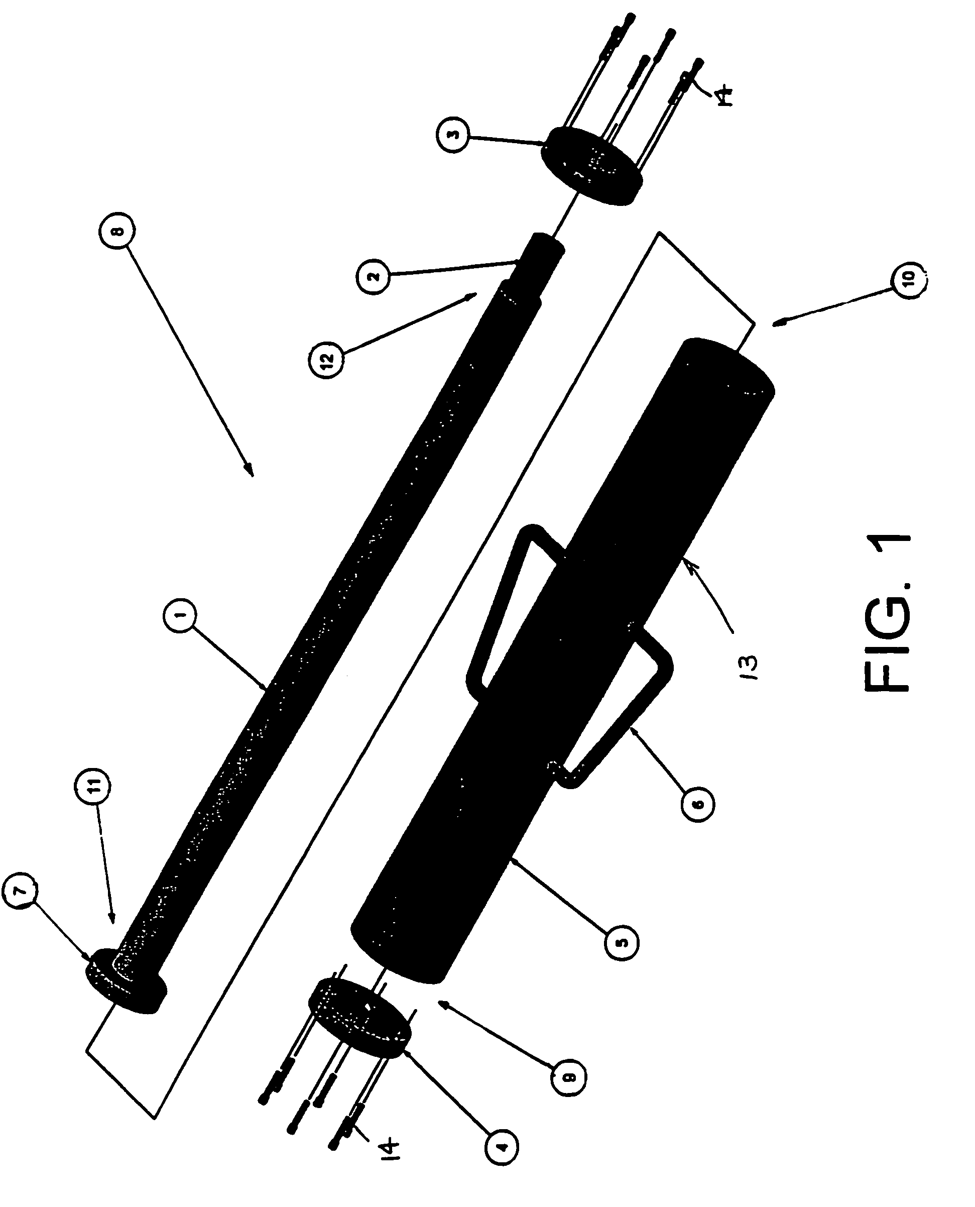
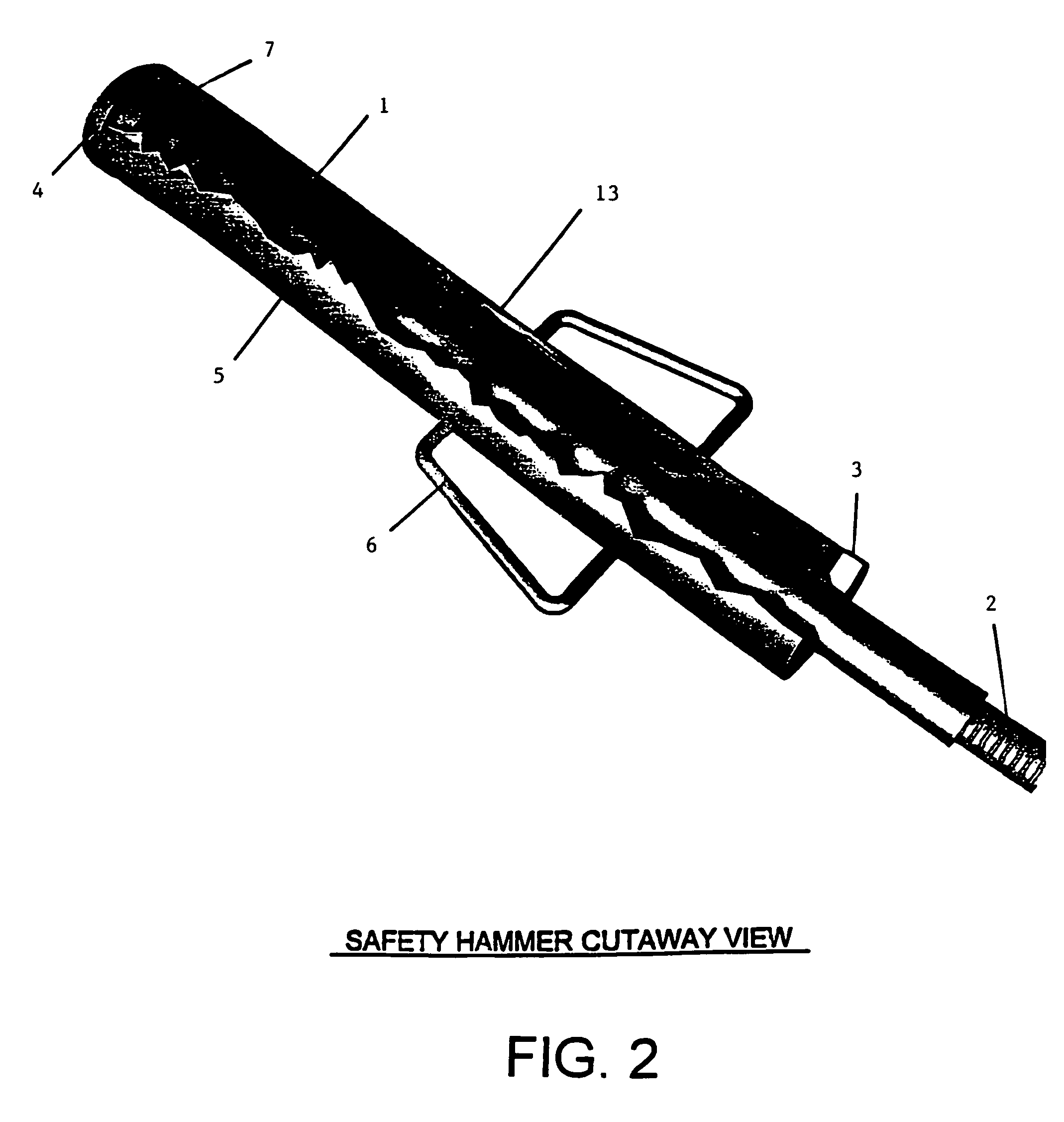
[0007]The DCP hammer of the present invention is capable of satisfying the standard “weight and drop height” requirements of the ASTM standard. However, the present DCP drive hammer differs from existing DCP drive hammers in that there are no exterior impact zones, thereby providing a DCP that is much safer to use. The impact zones of the present invention are completely interior, minimizing or eliminating any chance that a user may injure himself while using the DCP.
[0008]The preferred safety drive hammer assembly has a drive hammer and a rod. The rod has an end for attachment to a standard rod or dynamic cone penetrometer. The drive hammer assembly of the present invention has impact zones that are completely interior, eliminating any chance of user injury.
[0013]Preferably, handles may be fitted to the casing to improve portability without injuring the user during usage and transportation of a DCP. The casing end plate, and / or the top plate, may be bolted to the casing to permit periodic inspection, cleaning and maintenance of the interior of the drive hammer assembly.

Problems solved by technology

One problem with existing DCP's is that the two impact zones (the upper and lower steel rings that are the boundaries of the steel hammer's movement along the rod) are exposed.
A user often injures a finger or a hand by catching it in the line of travel of the steel hammer during use of the DCP.
A user may also be hurt by the movement of the steel hammer along the rod while transporting the DCP.

Method used


Image

  • Safety drive hammer for a dynamic cone penetrometer
  • Safety drive hammer for a dynamic cone penetrometer
  • Safety drive hammer for a dynamic cone penetrometer

Examples


Embodiment Construction

[0019]As shown in FIGS. 1–5, the present invention is a drive hammer assembly 8 used in performance of the dynamic cone penetrometer (DCP) test in accordance with ASTM STP-399.

[0020]In FIGS. 1–5, the safety drive hammer assembly 8 is a mechanical device comprising a drive hammer 13 and a rod 1. The rod 1 has an end 2 for attachment to a cone penetrometer that is used to measure the strength and the density of soil. The drive hammer assembly of the present invention is capable of satisfying the standard “weight and drop height” requirements of the ASTM standard. However, the present drive hammer differs from that of existing DCP's in that there are no exterior impact zones, thereby providing a DCP that is much safer to use. The impact zones of the present invention are completely interior, eliminating any chance that a user may injure himself while using the DCP. The dimensions for each of the elements of the invention detailed in this application are merely exemplary of, and inclusi...


PUM


Abstract

Drive hammer assembly with a drive hammer and rod is used with dynamic cone penetrometer tests. A rod end is attached to a cone penetrometer used to measure strength and density of soil. The assembly has no exterior impact zones, eliminating any chance of user injury. A casing loosely fits around a rod. A casing upper end is fitted with a top plate and lower end is fitted with an end plate through which the rod passes. Upper end of the rod is flared with a shoulder which may be welded to the top of the rod. Lower end of the rod is threaded to connect the rod to standard rod and cone assemblies. The hammer is raised to the shoulder on the upper end of the rod. The hammer slides along the rod until the top plate impacts upon the shoulder and drives the DCP cone into the ground.

Description

[0001]This application claims the benefit of U.S. Provisional Application Ser. No. 60 / 183,753, filed Feb. 22, 2000.BACKGROUND OF THE INVENTION[0002]Soil must be tested prior to beginning any construction to ascertain the strength and the density of the soil. One method of testing the strength and the density of soil is with a dynamic cone penetrometer (DCP). The DCP testing method has been standardized by the American Society for Testing and Materials in Special Technical Publication #399 (ASTM STP-399).[0003]Existing DCP's comprise a fifteen pound steel plate (hammer) that is slidably mounted on a steel rod, typically an “E drill” rod. The upper end of the rod is fitted with a first stationary steel ring. A second steel ring is mounted on the rod approximately twenty inches below the first steel ring. The hammer is lifted up to the upper ring and permitted to drop a height of twenty inches, at which point it impacts the lower ring, thereby driving the penetrating cone of the DCP de...

Claims


Application Information

Patent Timeline
IPC IPC(8): E02D1/02G01N3/00G01N3/42
CPCE02D1/022G01N3/42G01N2203/001G01N2203/0033
Inventor SAWYERS, J. MICHAEL
Owner SAWYERS J MICHAEL
Learn More