
Trailer hitch cover assembly

a trailer and cover technology, applied in the field of motor vehicles, can solve the problems of deformation of appearance or physical damage of the trailer hitch, and achieve the effect of reducing the possibility of physical damage to the trailer hitch and/or the motor vehicl

Inactive Publication Date: 2005-12-06
WALKER KENNETH
View PDF65 Cites 25 Cited by
  • Summary
  • Abstract
  • Description
  • Claims
  • Application Information

AI Technical Summary

Benefits of technology

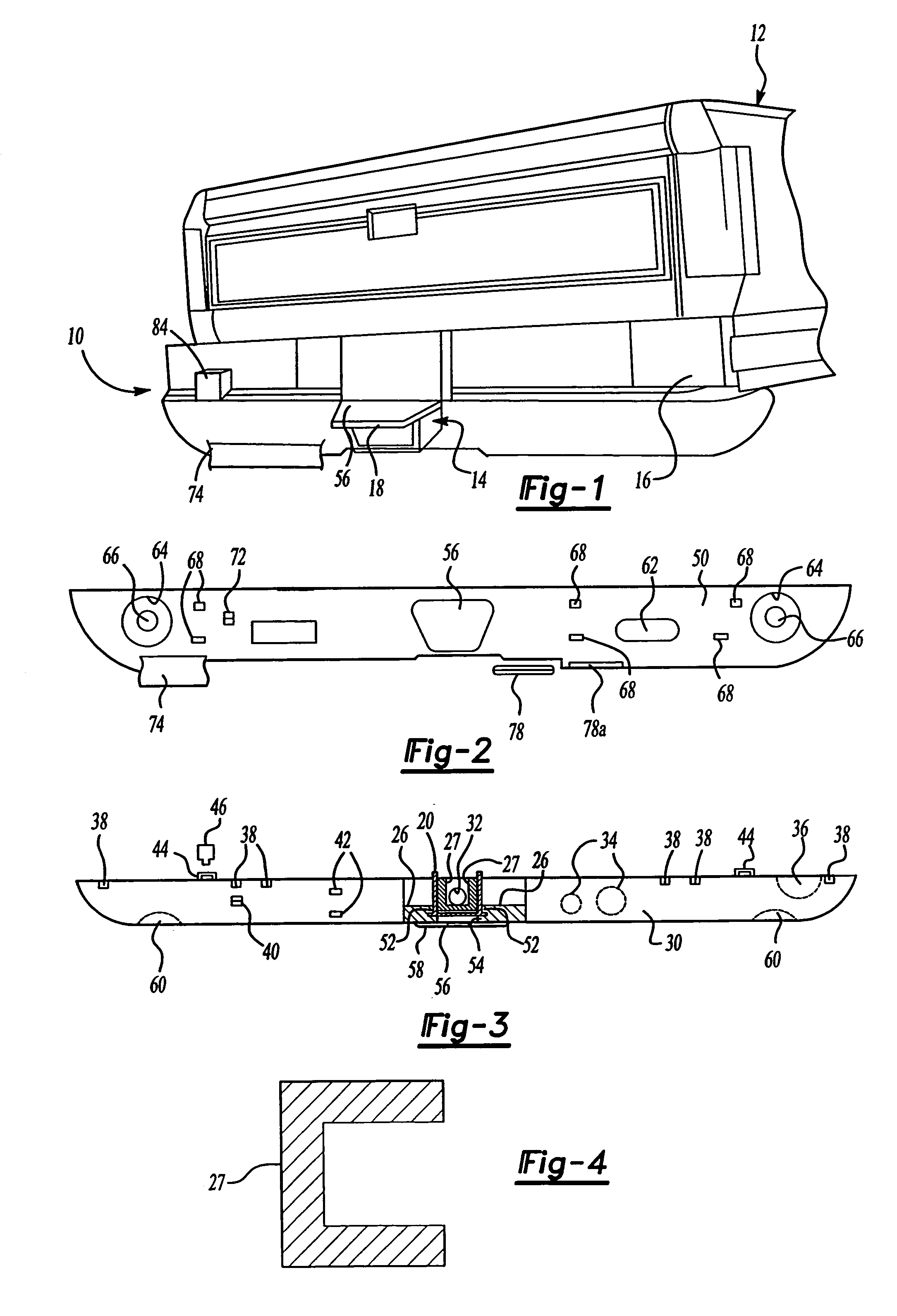
[0018]One advantage of the present invention is that a trailer hitch cover assembly is provided for a motor vehicle. Another advantage of the present invention is that the trailer hitch cover assembly shields the trailer hitch and motor vehicle against stones and debris from the road. Yet another advantage of the present invention is that the trailer hitch cover assembly provides a decorative appearance with additional taillight and / or reflectors to the motor vehicle and reduces the possibility of physical damage to the trailer hitch and / or motor vehicle. Still another advantage of the present invention is that the trailer hitch cover assembly includes an electronic signaling mechanism to supply a signal to a receiver, such as a toll booth PASS system. Still yet another advantage of the present invention is that the trailer hitch cover assembly includes an electronic locking pin as an additional safety feature. A further advantage of the present invention is that the trailer hitch cover assembly includes an anti-vibration mechanism to isolate the hitch tube from noise and vibration when towing. Still a further advantage of the present invention is that the trailer hitch cover assembly includes a spacer to more positively position the insert onto the hitch hook-up tube. Yet a further advantage of the present invention is that the trailer hitch cover assembly includes a pair of interlocking clamps that provides for access to the hitch tube with the cover in place. Still yet a further advantage of the present invention is that the trailer hitch cover assembly includes a step with a step support to reinforce the step. Yet still a further advantage of the present invention is that the trailer hitch cover assembly includes a hitch insert that is adjustable in a vertical direction.

Problems solved by technology

Although the above trailer hitch has worked well for towing a trailer by a motor vehicle, it suffers from the disadvantage that the trailer hitch is subjected to stones and other road debris forcefully hurled by the wheels of either the motor vehicle and / or trailer, which may result in degradation of appearance or physical damage to the trailer hitch.

Method used


Image

  • Trailer hitch cover assembly
  • Trailer hitch cover assembly
  • Trailer hitch cover assembly

Examples


embodiment 110

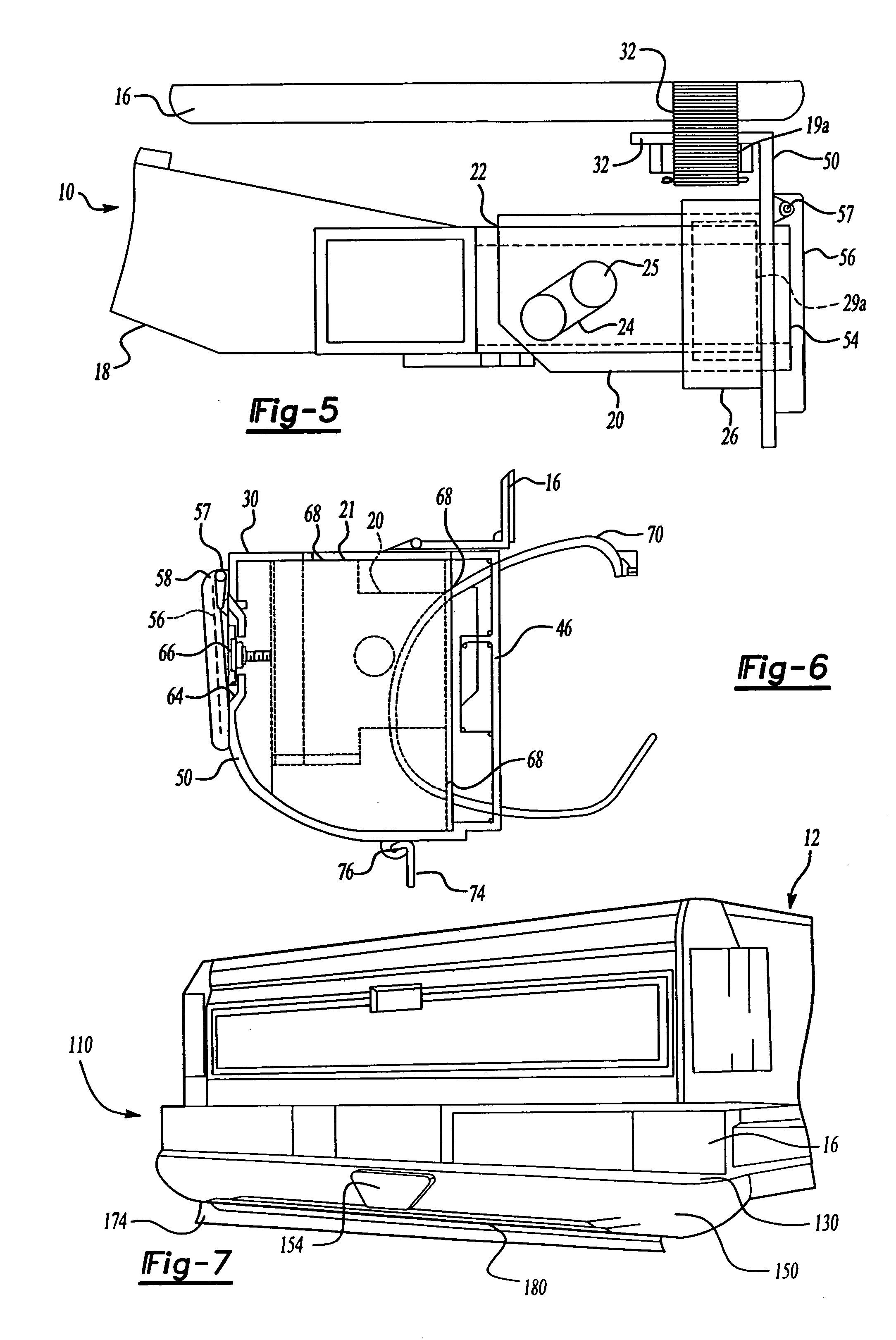
[0064]Referring to FIGS. 7 through 9, another embodiment 110, according to the present invention, of the trailer hitch cover assembly 10 is shown. Like parts of the trailer hitch cover assembly 10 have like reference numerals increased by one hundred. The trailer hitch cover assembly 110 includes a step 180 extending longitudinally and generally perpendicular to the front cover plate 150. The step 180 extends transversely a sufficient amount or predetermined length. The step 180 is supported by a support member 182 connected to the top cover plate 130 and has a reverse AL@ shape extending vertically and horizontally to extend under the step 180. The support 182 is made of a metal material. It should be appreciated that the front cover plate 150 extends downwardly and longitudinally from the step 180 to cover the trailer hitch 14 or undermount of motor vehicle application.

[0065]Referring to FIG. 10, yet another embodiment 210, according to the present invention, of the trailer hitch ...

embodiment 610

[0073]Referring to FIG. 19, still yet a further embodiment 610, according to the present invention, of the trailer hitch cover assembly 10 is shown. Like parts of the trailer hitch cover assembly 10 have like reference numerals increased by six hundred (600). The trailer hitch cover assembly 610 includes a top cover plate 630 and a front cover plate 650, that include all of the described features of the trailer hitch cover assembly 10. It should be appreciated that the top cover plate 630 and front cover plate 650 also function as a step. The front cover plate 630 may include one, and preferably a plurality of storage recesses 694 to form a storage box for the trailer hitch cover assembly 610. The storage recess 694 may be covered by a hingeable storage box cover 695. It should be appreciated that the storage box cover 695 may include a locking mechanism 696 to protect any contents that may be stored within the storage recess 694. Advantageously, the storage box cover 695 forms a se...

embodiment 710

[0075]Referring to FIGS. 20 and 21, still a further embodiment 710, according to the present invention, of the trailer hitch cover assembly 10 is shown. Like parts of the trailer hitch cover assembly 10 have like reference numerals increased by seven hundred (700). The trailer hitch cover assembly includes a hitch insert 720. The hitch insert 720 is generally rectangular in shape and has an aperture 722 extending longitudinally therethrough to fit over the hitch tube. The hitch insert 720 includes a flange 726, extending transversely on each side at a forward end of the aperture 722. The flange 726 includes a plurality of vertically arranged alignment apertures 726b for a function to be described.

[0076]The trailer hitch cover assembly includes a top cover plate 730. The top cover plate 730 extends transversely along the length of the rear bumper 716 and longitudinally a sufficient or predetermined appearance to provide a decorative appearance. The trailer hitch cover assembly also i...


PUM


Abstract

A trailer hitch cover assembly for a motor vehicle includes a hitch insert having an aperture extending longitudinally therethrough to fit over a hitch tube of a trailer hitch on a motor vehicle, and a rotatable door covering the aperture. The trailer hitch cover assembly also includes a top cover plate mounted to the hitch insert and a front cover plate mounted to the hitch insert and having an aperture extending therethrough aligned with the hitch tube of the trailer hitch.

Description

CROSS-REFERENCE TO RELATED APPLICATION(S)[0001]The present application is a divisional of U.S. Ser. No. 10 / 231,869, filed Aug. 29, 2002, now U.S. Pat. No. 6,719,318 which is a continuation of U.S. Ser. No. 09 / 716,666, filed Nov. 20, 2000 now U.S. Pat. No. 6,481,734, which is a continuation-in-part of U.S. Ser. No. 09 / 183,104, filed Oct. 30, 1998 now U.S. Pat. No. 6,176,506, which is a continuation-in-part of U.S. Ser. No. 08 / 795,481, filed Feb. 11, 1997, now U.S. Pat. No. 5,934,699.BACKGROUND OF THE INVENTION[0002]1. Field of the Invention[0003]The present invention relates generally to motor vehicles and, more particularly, to a trailer hitch cover assembly for a motor vehicle.[0004]2. Description of the Related Art[0005]It is known that motor vehicles may be provided with a trailer hitch to pull a trailer. Typically, the motor vehicle has a trailer hitch having a hitch tube secured to the motor vehicle beneath the bumper and a ball connector having an insert tube disposed in the h...

Claims


Application Information

Patent Timeline
Patent Type & Authority Patents(United States)
IPC IPC(8): B60D1/60
CPCB60D1/60
Inventor BLAKE, ROBERT B.
Owner WALKER KENNETH
Learn More