
Methods and apparatus for exhausting gases from gas turbine engines

a gas turbine engine and gas exhaust technology, applied in the field of gas turbine engines, can solve the problems of substantial engine power loss or weight penalty, infrared-guided missiles, and helicopters are susceptible to ground-to-air, and achieve the effect of suppressing the infrared signatur

Active Publication Date: 2005-12-06
GENERAL ELECTRIC CO
View PDF9 Cites 19 Cited by
  • Summary
  • Abstract
  • Description
  • Claims
  • Application Information

AI Technical Summary

Benefits of technology

[0005]In one aspect, a method for assembling a gas turbine engine is provided. The method comprises mounting a core engine to a vehicle, coupling a fuselage radially outward and around the core engine, and coupling an exhaust nozzle to the core engine to channel exhaust gases discharged from the core engine. In addition, the method also comprises coupling an infrared suppression system in flow communication with the engine exhaust nozzle for channeling exhaust gases discharged from said exhaust nozzle to facilitate suppressing an exhaust infrared signature of the core engine during operation, wherein the infrared suppression system includes an access door and a flow channel that is coupled to the access door such that the flow channel is movable with the access door from a closed position to an open position.
[0006]In another aspect, an exhaust assembly for a gas turbine engine including a turbine rear frame is provided. The exhaust assembly includes an engine exhaust nozzle extending downstream from the turbine rear frame, and an infrared suppression system coupled in flow communication with the engine exhaust nozzle for channeling exhaust gases discharged from the exhaust nozzle. The suppression system includes a flow channel coupled to an access door, such that the flow channel is movable with the access door from a closed position to an open position wherein the access door forms a work platform configured to support a user thereon. The suppression system facilitates suppressing an exhaust infrared signature of the gas turbine engine.

Problems solved by technology

Because the military mission of helicopters may involve flying at low altitudes and at reduced speed in comparison to other military aircraft, helicopters are susceptible to ground-to-air, infrared-guided missiles.
Moreover, continued heating of aircraft surfaces, including the fuselage, during hover or flight may also create structural issues.
More specifically, at least some known gas turbine engines use complicated cooling schemes to supply cooling air to facilitate cooling directly visible surfaces and to dilute the high temperature exhaust gases.
However, generally, any benefits gained by such systems may be offset by losses created in acquiring the reduced infrared signature.
More specifically, when the exhaust gases are cooled by cooling air, the air may be provided at a substantial engine power loss or weight penalty.
Furthermore, in other known systems, the benefits gained by such systems may be offset by comparatively large installation space requirements, complex ducting, and / or substantial weight penalties.
Moreover, the weight and physical size of such suppression systems may limit access to the gas turbine engine for routine maintenance and inspections.

Method used


Image

  • Methods and apparatus for exhausting gases from gas turbine engines
  • Methods and apparatus for exhausting gases from gas turbine engines
  • Methods and apparatus for exhausting gases from gas turbine engines

Examples


Embodiment Construction

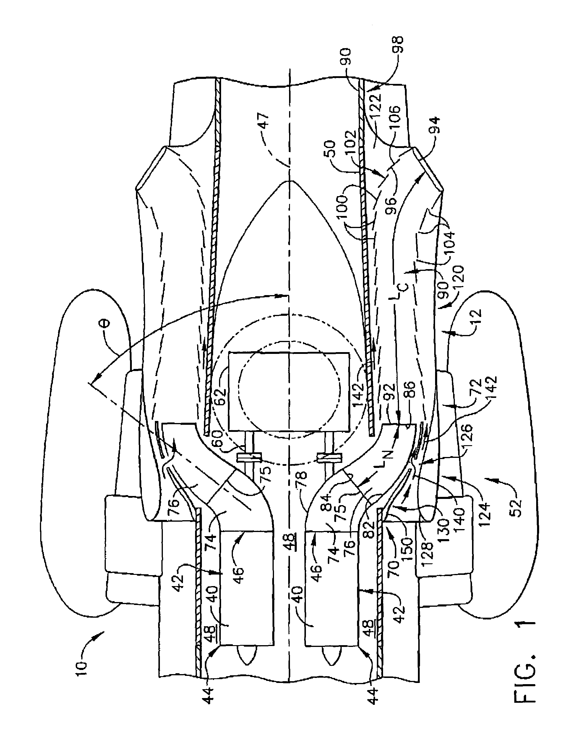
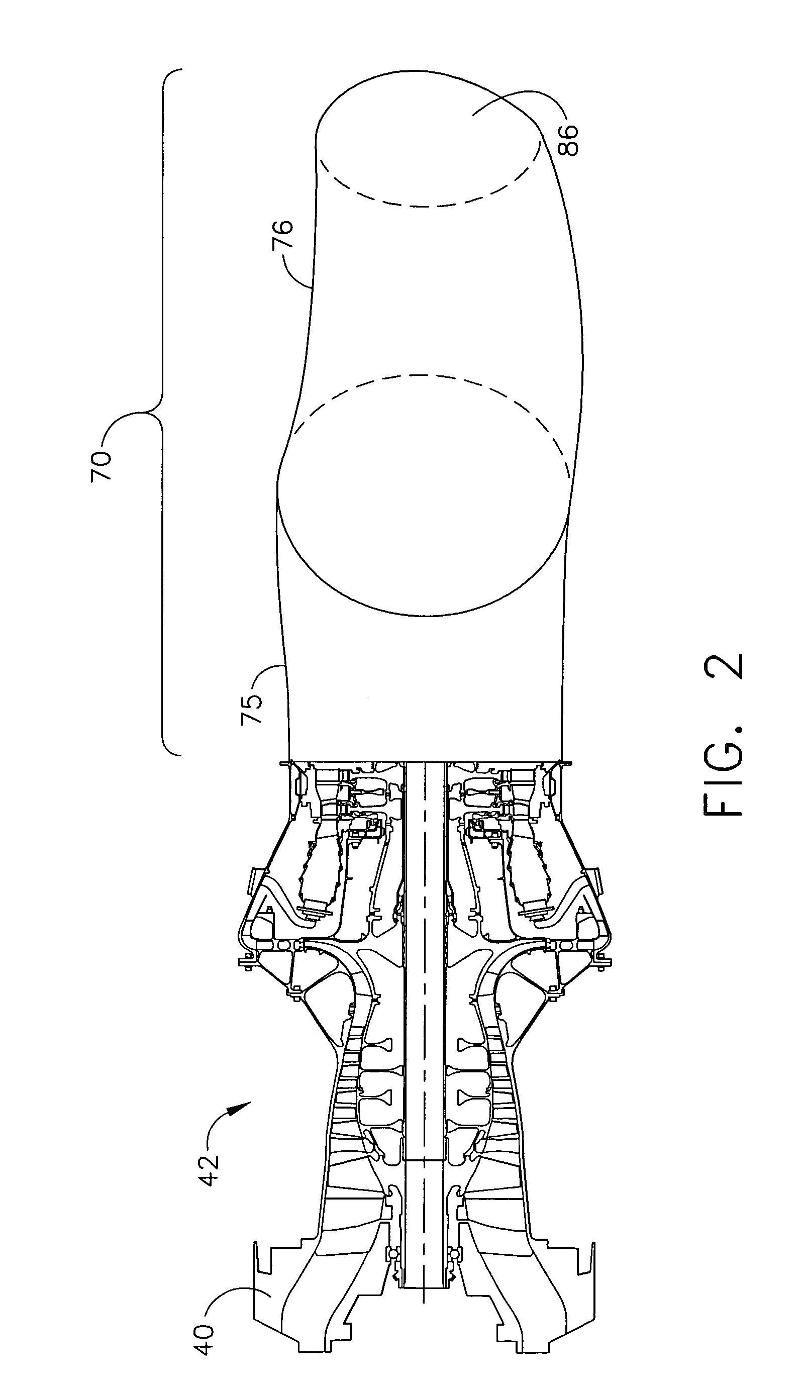
[0015]FIG. 1 is a plan view of a helicopter 10 that includes two gas turbine engine assemblies 42 and access doors 12. FIG. 2 is a perspective view of a core engine 40 and exhaust nozzle 76 that may be used with gas turbine engine assembly 42. FIG. 3 is a partial front view of an exemplary helicopter 14 including access door 12 shown in a closed position 16. FIG. 4 is a partial front view of helicopter 14 including access door 12 shown in an open position 22. FIGS. 5, 6, and 7 are alternative embodiments of turbine exhaust nozzles 76 that may be used with gas turbine engine assembly 42.

[0016]In the exemplary embodiment, helicopter 14 includes a pair of gas turbine engines 40 that each include an inlet end 44 and an exhaust end 46. Engines 40 are symmetrical with respect to an axis of symmetry 47 extending between engines 40. Core engines 40 are mounted within an engine compartment 48 defined by a helicopter fuselage 50. Specifically, in the exemplary embodiment, gas turbine engine a...


PUM


Abstract

A method facilitates assembling a gas turbine engine. The method comprises mounting a core engine to a vehicle, coupling a fuselage radially outward and around the core engine, and coupling an exhaust nozzle to the core engine to channel exhaust gases discharged from the core engine. In addition, the method also comprises coupling an infrared suppression system in flow communication with the engine exhaust nozzle for channeling exhaust gases discharged from said exhaust nozzle to facilitate suppressing an exhaust infrared signature of the core engine during operation, wherein the infrared suppression system includes an access door and a flow channel that is coupled to the access door such that the flow channel is movable with the access door from a closed position to an open position.

Description

BACKGROUND OF THE INVENTION[0001]This invention relates generally to gas turbine engines, and more specifically to methods and apparatus for exhausting gases from gas turbine engines.[0002]The exhaust nozzle and plume from gas turbine engines is a potential source of high infrared energy which may be used for targeting and / or tracking purposes. More specifically, the infrared energy may be used for targeting and / or tracking by heat seeking missiles and / or various forms of infrared imaging systems. Because the military mission of helicopters may involve flying at low altitudes and at reduced speed in comparison to other military aircraft, helicopters are susceptible to ground-to-air, infrared-guided missiles. For example, within at least some known helicopters, the exposed metal surfaces of the gas turbine engine exhaust may operate in excess of 800° F., and thus emit infrared electromagnetic radiation at virtually all wavelengths as hot exhaust gases flow past the exposed surfaces. ...

Claims


Application Information

Patent Timeline
Patent Type & Authority Patents(United States)
IPC IPC(8): B64D29/08B64D33/04F02K1/46F02K1/52F02K1/82
CPCB64D33/04F02K1/825B64D2033/045
Inventor WOLLENWEBER, GARY C.
Owner GENERAL ELECTRIC CO
Learn More