
Current control apparatus for fluorescent lamps

a technology of current control apparatus and fluorescent lamps, which is applied in the direction of electric variable regulation, process and machine control, instruments, etc., can solve the problems of increased circuit board size, increased cost, and increased manufacturing difficulty

Inactive Publication Date: 2005-11-29
ZIPPY TECH
View PDF4 Cites 4 Cited by
  • Summary
  • Abstract
  • Description
  • Claims
  • Application Information

AI Technical Summary

Benefits of technology

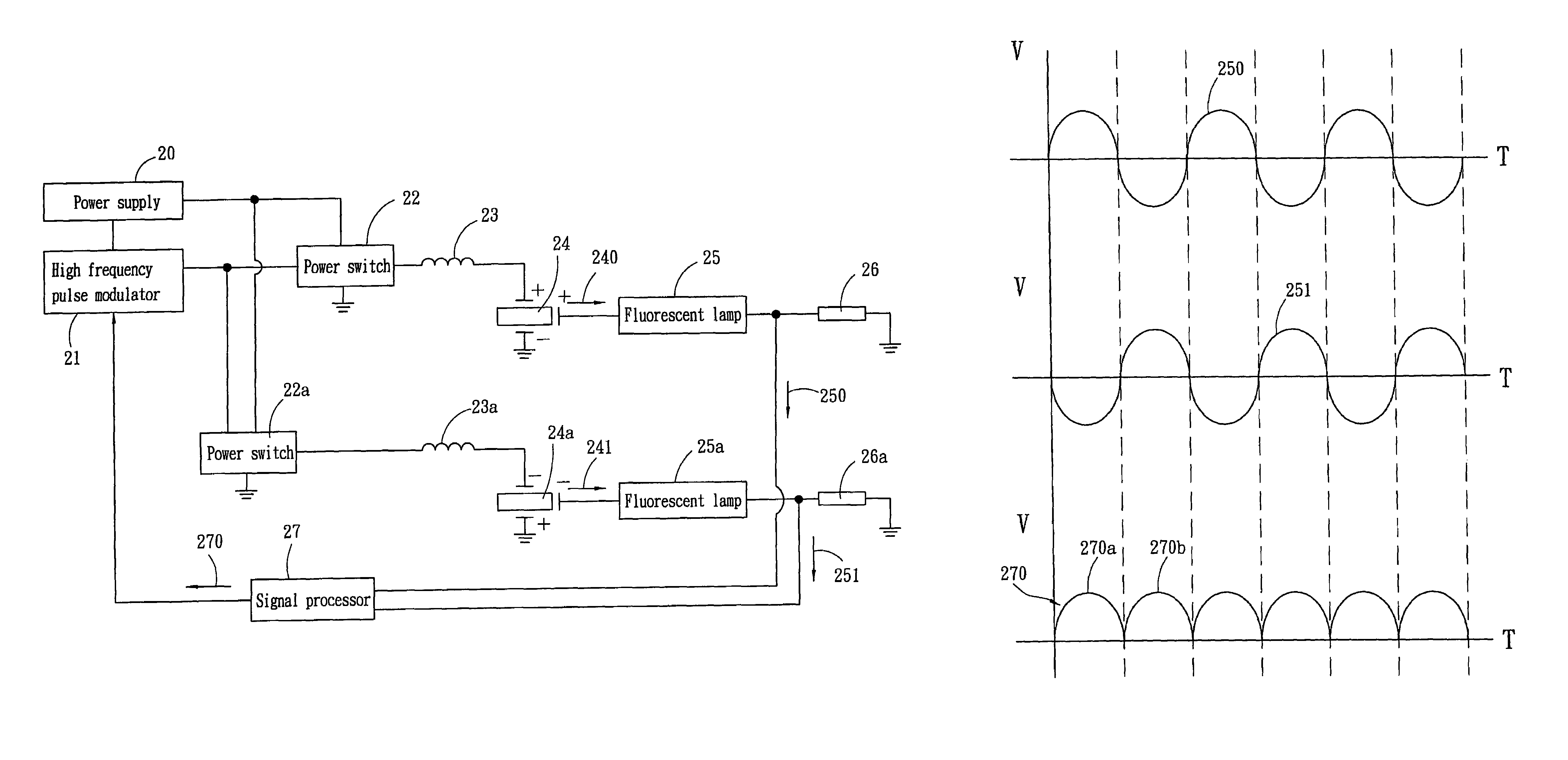
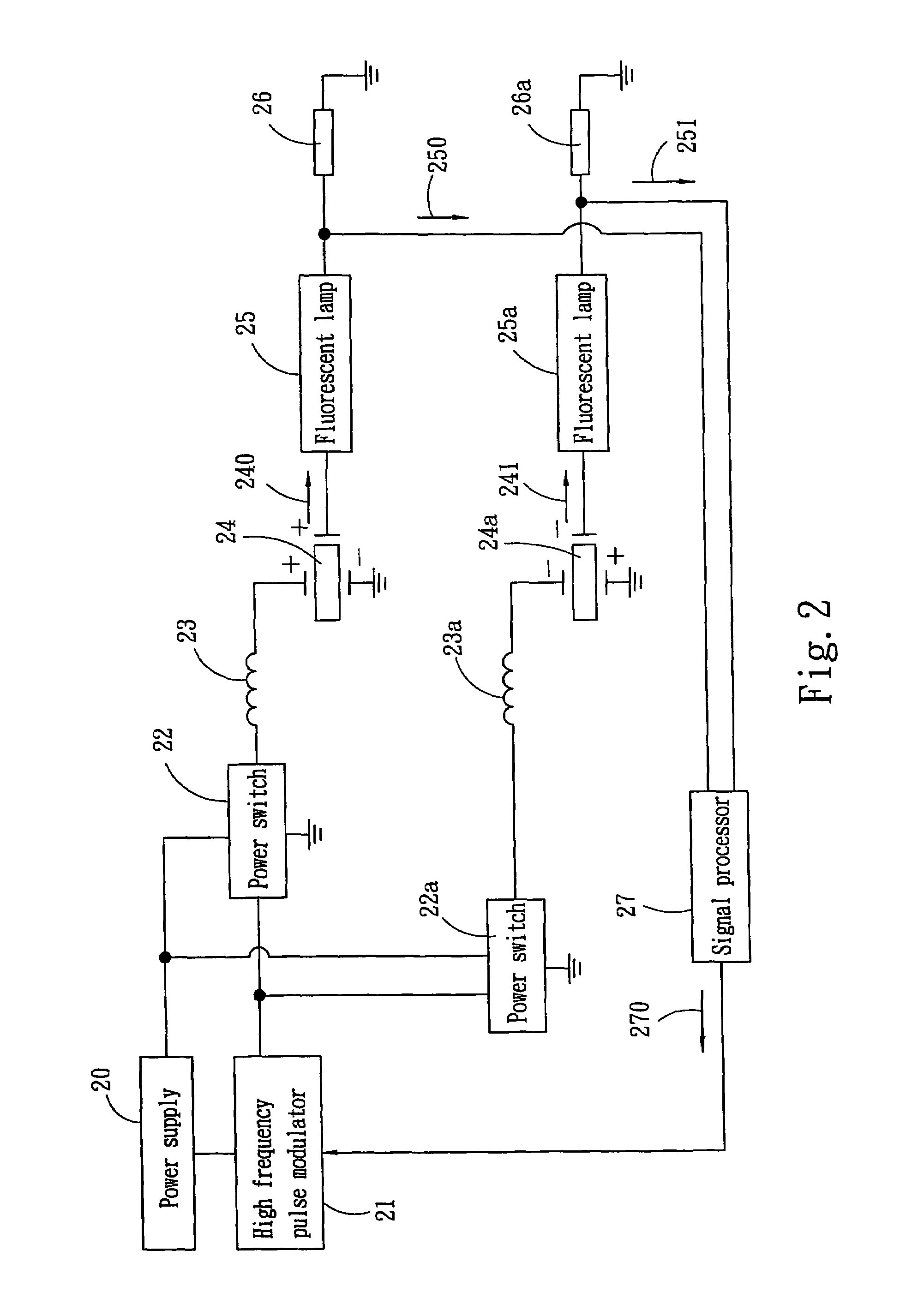
"The present invention provides a current control apparatus for fluorescent lamps that can maintain even current through a current feedback approach. Another approach uses a signal processor to detect output current of the fluorescent lamps and output a current compensation signal to a high frequency pulse modulator to redistribute the current. This apparatus can be used on high voltage actuated fluorescent lamps to maintain current evenness. The apparatus includes a high frequency pulse modulator, a power switch, a conversion unit, a piezoelectric transformer, and a fluorescent lamp. The main features of the invention include dividing the fluorescent lamp to a positive phase and an inverted phase, actuating the lamps with a positive half cycle and a negative half cycle actuation signals, detecting output current of the lamps through a signal generator, and outputting a resonant frequency to control current variation of the lamps."

Problems solved by technology

In such an occasion, the most important issue is to maintain the evenness of lamp current among the loads or minimize the characteristic tolerance among them.
As a result, the size of the circuit board increases.
Fabrication is more difficult and cost is higher.
In the event that a plurality of fluorescent lamps are used to increase the luminosity and evenness, because of the tolerance of the fluorescent lamps, uneven tube current and luminosity often occur to the fluorescent lamps.
It makes selection of the fluorescent lamps more difficult or results in more fluorescent lamps are needed to improve the luminosity and evenness.
Hence the cost becomes even higher, and fabrication and adjustment are even more difficult.
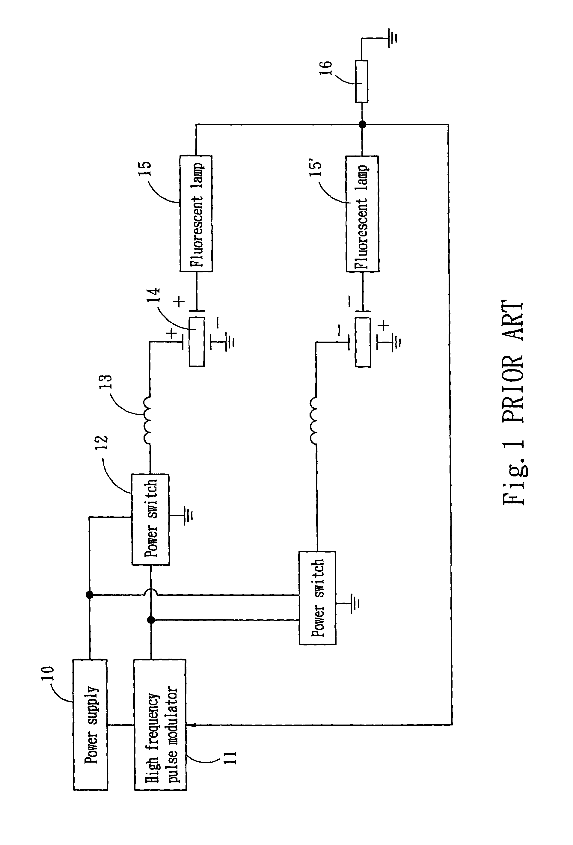
Hence it is not possible to feed back a voltage signal to the high frequency pulse modulator 11.
Therefore it is not possible to control the current of the fluorescent lamps 15 and 15′ through a voltage feedback circuit.
Moreover, the conventional fluorescent lamps 15 and 15′ also have other problems, such as unstable electrodes, gas, and the like.
They will cause abnormal operation of the current in the fluorescent lamps 15 and 15′ (such as power loss).
This phenomenon tends to result in power loss or damages of the fluorescent lamps 15 and 15′.

Method used


Image

  • Current control apparatus for fluorescent lamps
  • Current control apparatus for fluorescent lamps
  • Current control apparatus for fluorescent lamps

Examples


Embodiment Construction

[0018]The current control apparatus according to the invention is adopted for use on a high voltage actuated fluorescent lamp to maintain normal operation of the current in the fluorescent lamp (CCFL) to avoid abnormal current occurred to the fluorescent lamp when actuated by a high voltage.

[0019]Refer to FIG. 2 for a current control circuit diagram of the invention. It is for use on fluorescent lamps (as shown in the FIG. 2) 25 and 25a actuated by a high voltage to maintain evenness of the current in the fluorescent lamps 25 and 25a. It includes:[0020]a high frequency pulse modulator 21 to receive operation voltage input from a power supply 20 and provide voltage distribution signals and transmit a pulse width modulation (PWM) resonant frequency signal through PWM;[0021]a power switch (as shown in FIG. 2) 22 and 22a controlled by a positive half cycle signal and a negative half cycle signal of the PWM resonant frequency signal and outputs an actuation signal;[0022]a conversion unit...


PUM


Abstract

A current control apparatus for fluorescent lamps adopted for use on high voltage actuated a fluorescent lamp includes a high frequency pulse modulator to provide voltage distribution signals, a power switch which is a MOSFET to output actuation signals, a conversion unit to receive the voltage distribution signals and perform voltage transformation, a piezoelectric transformer to receive the transformed voltage and perform voltage transformer, and the fluorescent lamp connecting to the piezoelectric transformer. The high frequency pulse modulator obtains a feedback current from the output ends of the fluorescent lamps through the signal processor to redistribute current and maintain evenness of the current in the fluorescent lamp.

Description

FIELD OF THE INVENTION[0001]The present invention relates to a current control apparatus for fluorescent lamps and particularly to a current control apparatus that maintains even current in a fluorescent lamp through a current feedback control approach.BACKGROUND OF THE INVENTION[0002]At present the light source used by liquid crystal display (LCD) of desktop computers and notebook computers, PDA, and Webpad generally is a fluorescent lamp (such as cold cathode fluorescent lamp—CCFL) actuated by a high voltage. Light is projected to a backlight plate to enable users to see the displaying picture.[0003]LCD TV or LCD display screen with a touch film requires a greater luminosity to compensate visual requirement. As the fluorescent lamp is driven by a high voltage, when the current is higher, the luminosity also is greater. Moreover, in order to increase the luminosity, a plurality of fluorescent lamps are often being used. In such an occasion, the most important issue is to maintain t...

Claims


Application Information

Patent Timeline
Patent Type & Authority Patents(United States)
IPC IPC(8): G05F1/00H05B37/00H05B37/02H05B41/282
CPCH05B41/2822
Inventor CHOU, CHIN-WENCHENG, EDDIECHUNG, CHIN-BIAU
Owner ZIPPY TECH
Learn More