Grappler control system for a gantry crane
- Summary
- Abstract
- Description
- Claims
- Application Information
AI Technical Summary
Benefits of technology
Problems solved by technology
Method used
Image
Examples
Embodiment Construction
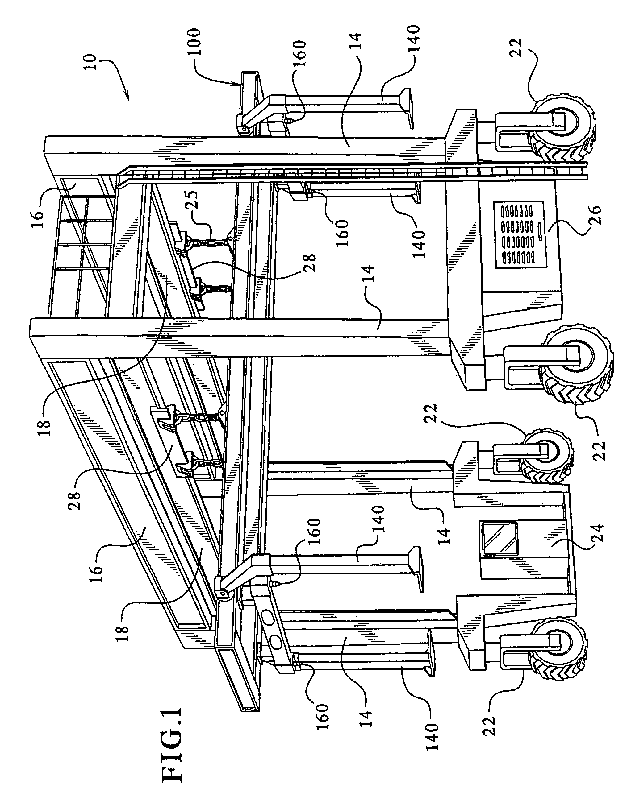
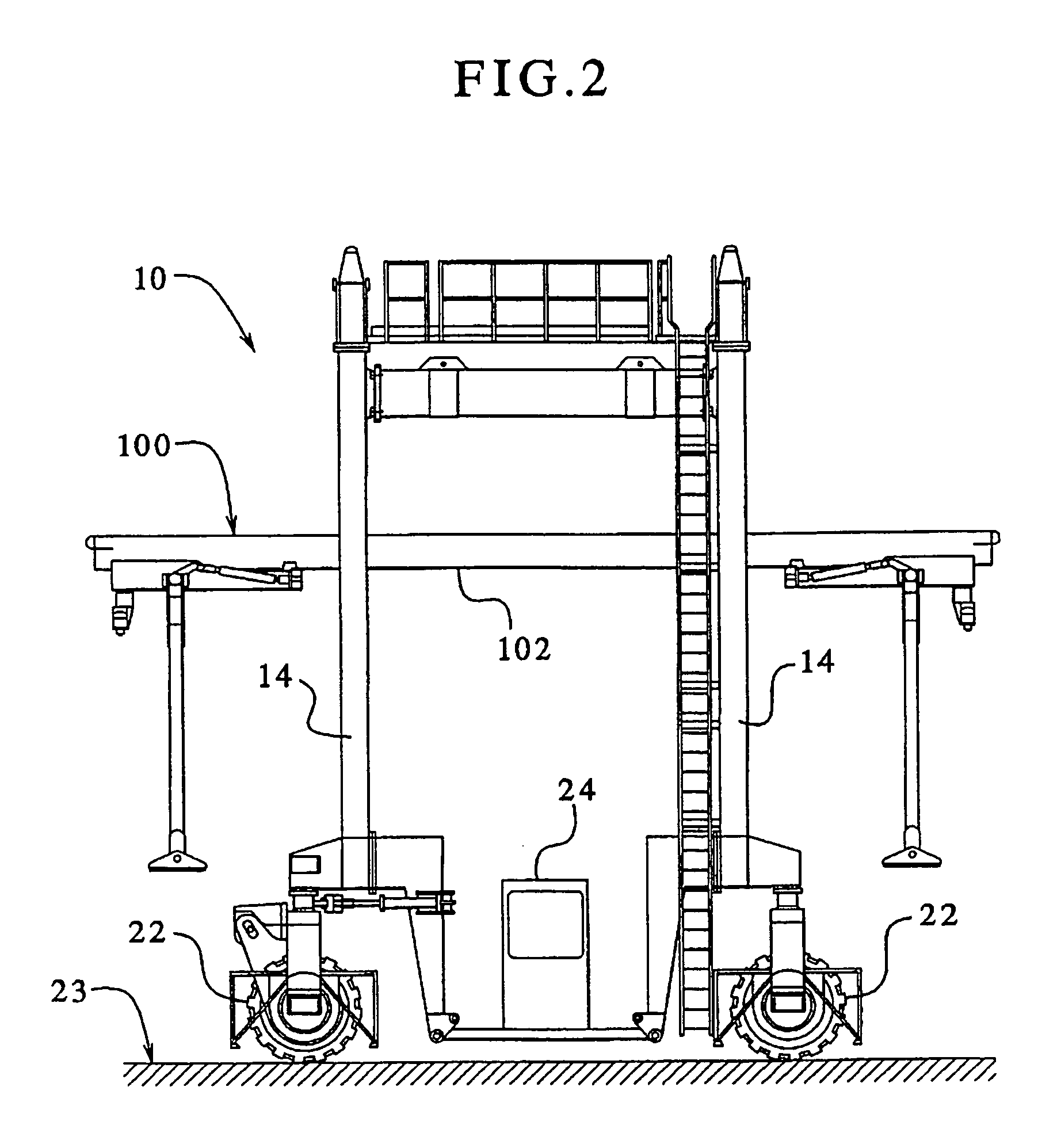
[0031]Now turning to the drawings, FIGS. 1, 2 and 3 illustrate an exemplary gantry crane 10. The illustrated gantry crane 10 includes a frame structure having four generally vertical columns 14, and front and rear support beams 16 rigidly mounted to extend generally horizontally between respective pairs of the columns. For engaging an object to be lifted, the crane includes a grappler 100, which will be described in greater detail below.
[0032]Although stationary cranes are known, cranes are commonly provided as mobile units adapted for maneuvering on a pavement. For example, as illustrated in FIG. 1, the crane 10 is equipped with a plurality of wheel assemblies 22 having rubber tires to support the columns 14. The wheel assemblies 22 are actuatable to drive, steer and maneuver the crane 10 on a pavement surface in a desired manner. Such a mobile crane is generally referred to in the industry as a rubber-tired gantry, or RTG.
[0033]Referring to FIGS. 1 and 2, the crane 10 includes a c...
PUM
 Abstract
Description
Claims
Application Information
 - R&D
- Intellectual Property
- Life Sciences
- Materials
- Tech Scout
- Unparalleled Data Quality
- Higher Quality Content
- 60% Fewer Hallucinations
Browse by: Latest US Patents, China's latest patents, Technical Efficacy Thesaurus, Application Domain, Technology Topic, Popular Technical Reports.
© 2025 PatSnap. All rights reserved.Legal|Privacy policy|Modern Slavery Act Transparency Statement|Sitemap|About US| Contact US: help@patsnap.com


