
Tissue ablation device assembly and method for electrically isolating a pulmonary vein ostium from an atrial wall

Inactive Publication Date: 2005-11-22
ATRIONIX
View PDF226 Cites 249 Cited by
  • Summary
  • Abstract
  • Description
  • Claims
  • Application Information

AI Technical Summary

Benefits of technology

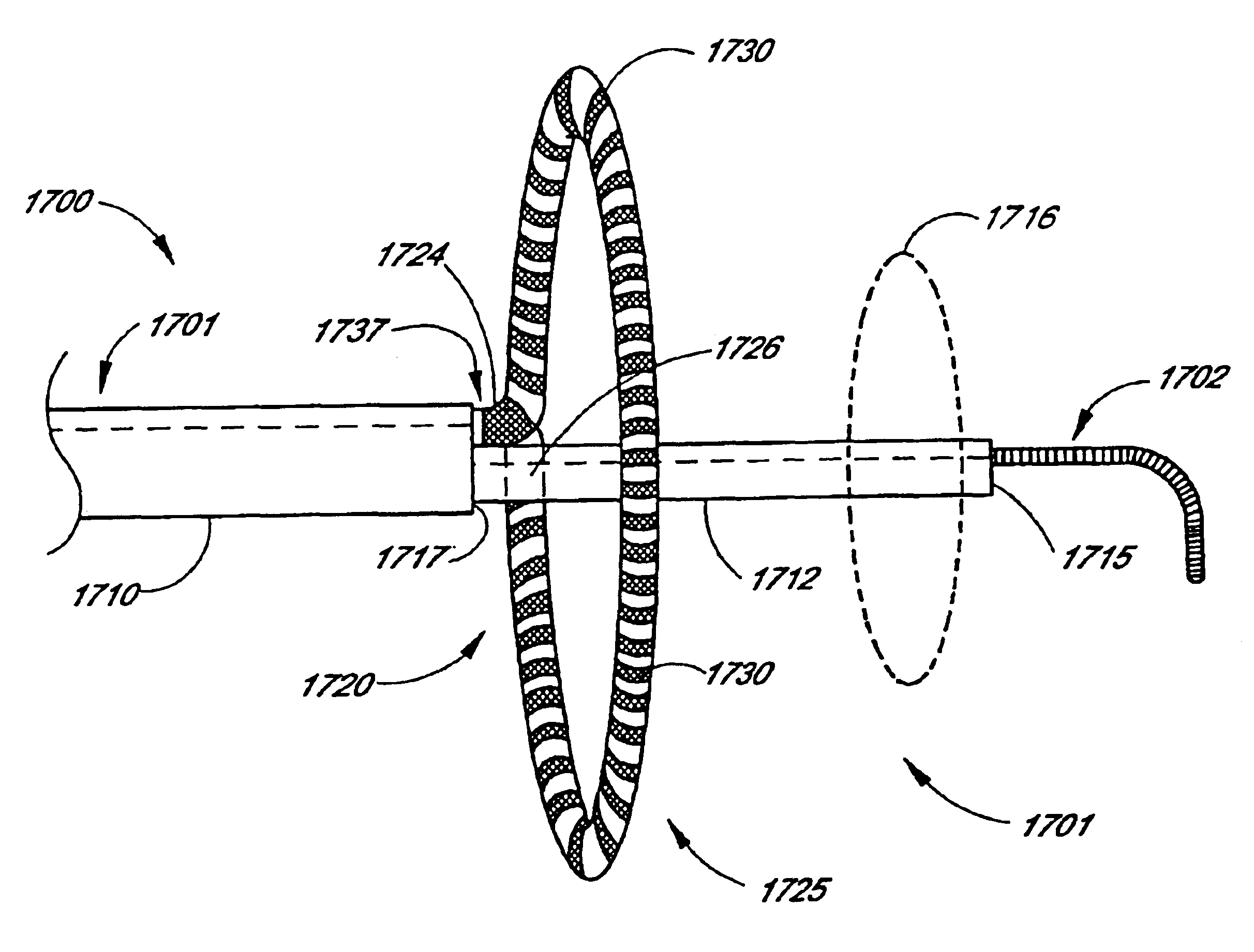
[0032]According to another mode of the invention, a circumferential ablation member coupled to the distal end portion of a delivery member includes an array of splines supporting an array of individual ablation elements with each ablation element being supported along a support region of one of the splines. The splines are circumferentially spaced around the longitudinal axis. Each spline is adjustable between a first condition and a second condition, wherein the respectively supported individual ablation element is adjustable between a first radial position and a second radial position. Further to this assembly, each spline is substantially radially collapsed and extends substantially along the longitudinal axis in the first condition such that the circumferential ablation member is adapted to be delivered through a delivery s

Problems solved by technology

Cardiac arrhythmias, and atrial fibrillation in particular, persist as common and dangerous medical ailments, especially in the aging population.

Method used


Image

  • Tissue ablation device assembly and method for electrically isolating a pulmonary vein ostium from an atrial wall
  • Tissue ablation device assembly and method for electrically isolating a pulmonary vein ostium from an atrial wall
  • Tissue ablation device assembly and method for electrically isolating a pulmonary vein ostium from an atrial wall

Examples


Embodiment Construction

[0141]The terms “body space,” including derivatives thereof, is herein intended to mean any cavity or lumen within the body that is defined at least in part by a tissue wall. For example, the cardiac chambers, the uterus, the regions of the gastrointestinal tract, and the arterial or venous vessels are all considered illustrative examples of body spaces within the intended meaning.

[0142]The term “lumen,” including derivatives thereof, is herein intended to mean any body space which is circumscribed along a length by a tubular tissue wall and which terminates at each of two ends in at least one opening that communicates externally of the body space. For example, the large and small intestines, the vas deferens, the trachea, and the fallopian tubes are all illustrative examples of lumens within the intended meaning. Blood vessels are also herein considered lumens, including regions of the vascular tree between their branch points. More particularly, the pulmonary veins are lumens with...


PUM

PropertyMeasurementUnit
Electrical conductivityaaaaaaaaaa
Areaaaaaaaaaaa
Electrical currentaaaaaaaaaa

Abstract

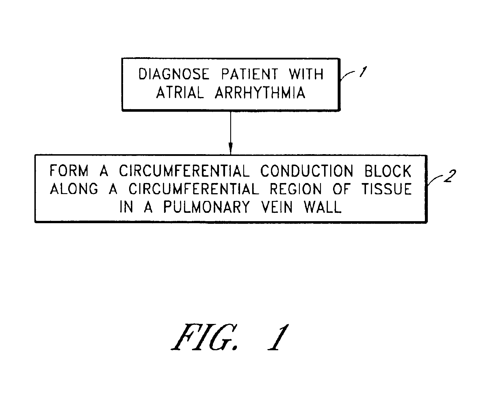
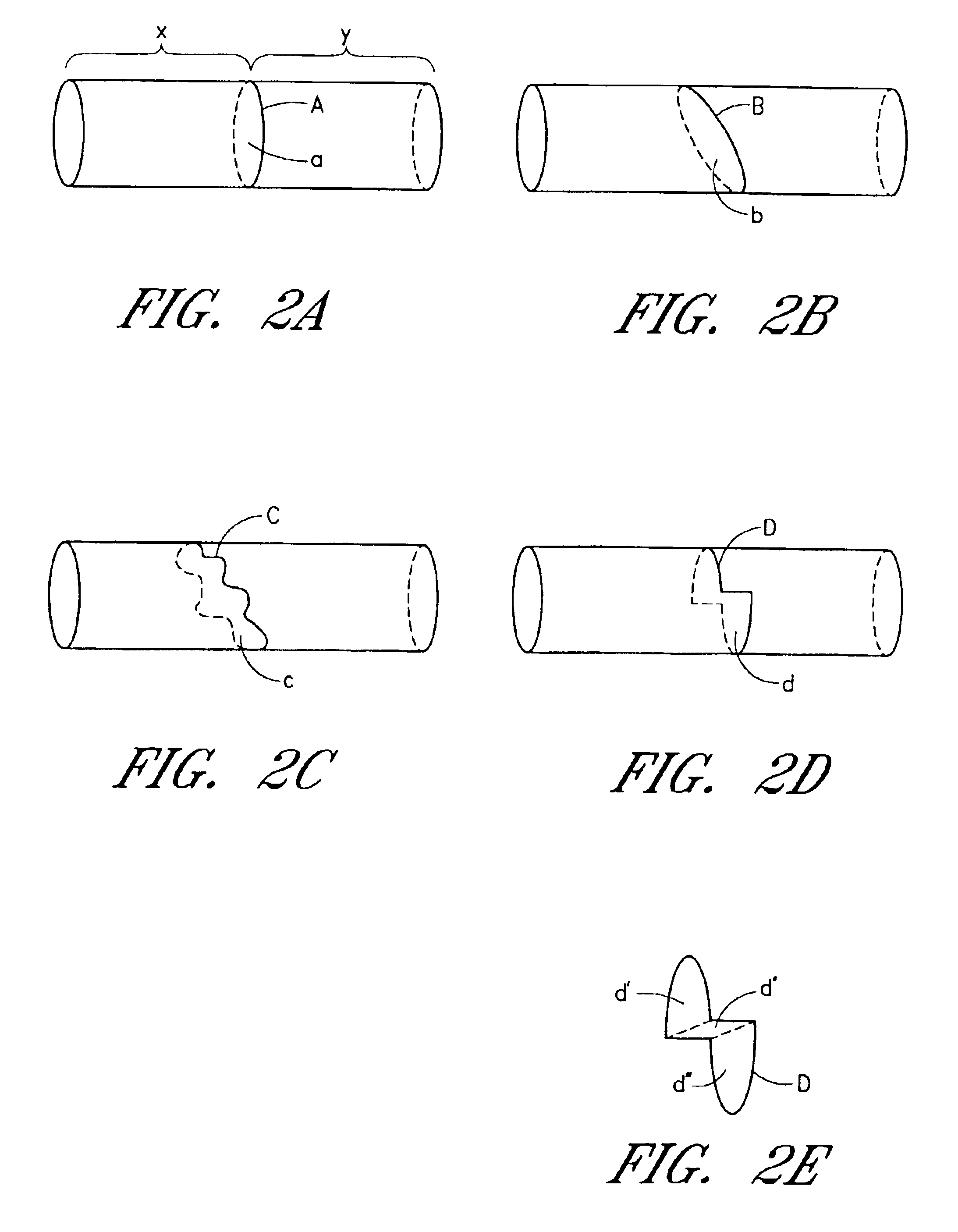
This invention is related to a tissue ablation system and method that treats atrial arrhythmia by ablating a circumferential region of tissue at a location where a pulmonary vein extends from an atrium. The system includes a circumferential ablation member with an ablation element and also includes a delivery assembly for delivering the ablation member to the location. The circumferential ablation member is generally adjustable between different configurations to allow both the delivery through a delivery sheath into the atrium and the ablative coupling between the ablation element and the circumferential region of tissue.

Description

RELATED APPLICATIONS[0001]This application is a divisional of U.S. patent application Ser. No. 09 / 435,281 filed on Nov. 5, 1999, now U.S. Pat. No. 6,652,515, to which this application claims priority under 35 U.S.C. § 121. U.S. patent application Ser. No. 09 / 435,281 is a continuation-in-part of U.S. patent application Ser. No. 08 / 889,798 filed on Jul. 8, 1997, now U.S. Pat. No. 6,024,740; and is a continuation-in-part of Ser. No. 09 / 199,736 filed on Nov. 25, 1998, now U.S. Pat. No. 6,117,101, to which this application also claims priority under 35 U.S.C. § 120. This application also claims priority pursuant to 35 U.S.C. § 119(e) to provisional application 60 / 133,677 filed on May 11, 1999.BACKGROUND OF THE INVENTION[0002]1. Field of the Invention[0003]The present invention relates to a surgical device and method. More specifically, it is a device assembly and method adapted to form a circumferential conduction block along a circumferential region of tissue along a posterior left atri...

Claims


Application Information

Patent Timeline
IPC IPC(8): A61B18/14A61B18/00A61N7/02A61N7/00A61B18/08A61B18/04A61M25/10A61B17/00A61F2/958
CPCA61B18/00A61B18/1492A61N7/02A61B18/08A61B18/1815A61B2017/00243A61B2017/22038A61B2017/22054A61B2017/22067A61B2018/00011A61B2018/00065A61B2018/00101A61B2018/00148A61B2018/0016A61B2018/00214A61B2018/00232A61B2018/00238A61B2018/00273A61B2018/00285A61B2018/00291A61B2018/00369A61B2018/00375A61B2018/00797A61B2018/00815A61B2018/00821A61B2018/00839A61B2018/00898A61B2018/00994A61B2018/143A61B2018/1432A61B2218/002A61M25/1002
Inventor MAGUIRE, MARK A.LESH, MICHAEL D.PEACOCK, III, JAMES C.CARCAMO, EDWARD L.
Owner ATRIONIX
Learn More